
DChV-2500
Speed Inductive Sensor


Description
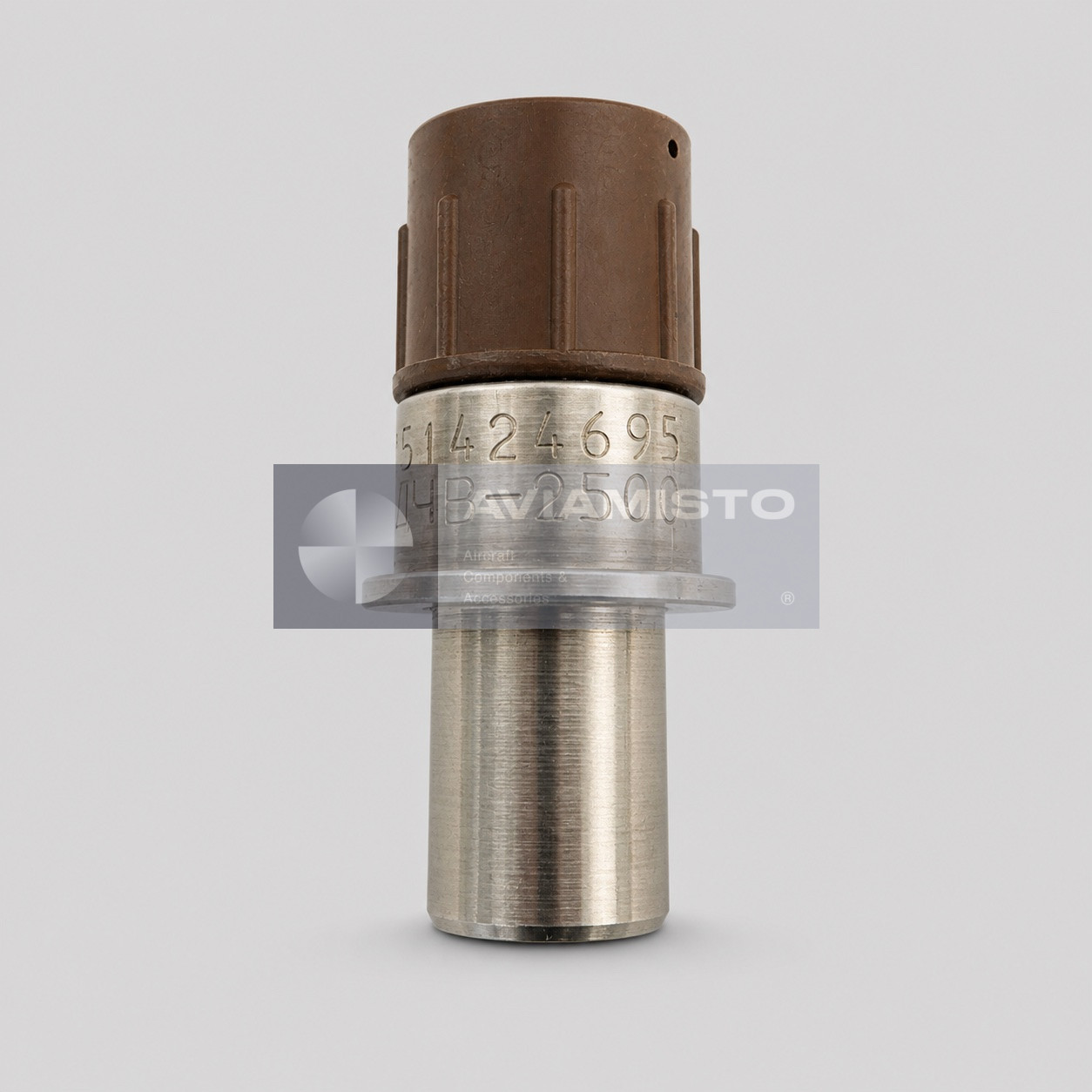
DChV-2500 speed inductive transducer
DChV-2500 is a two-channel speed inductive transducer used to convert the rotational speed of an aircraft gas-turbine engine rotor into an electrical pulse frequency. The original Russian designation is ДЧВ-2500. Technical literature for the TV3-117 engine describes the unit as a passive electromagnetic sensor with two electrically independent circuits. Each circuit can provide a speed signal to compatible monitoring, control or protection equipment. The sensor is therefore an engine-instrumentation component, not a self-contained cockpit indicator. The related DChV-2500A is used as an interchangeable execution; the complete designation, connector, mounting flange and supplied documentation should still be checked before installation.
Full descriptionCollapse description
Function in the engine monitoring system
The transducer works with a toothed inductor that forms part of the engine installation. As the inductor rotates past the magnetic pole of the sensor, the magnetic circuit changes periodically and an alternating voltage is induced in each winding. The frequency of the resulting pulses is proportional to rotor speed. The inductor is not included in the DChV-2500 transducer delivery set, so the sensor must be matched to the correct engine gear, operating gap and wiring circuit defined by the maintenance manual.
Published training documentation describes an engine instrumentation arrangement using five sensors: two on the low-pressure rotor drive, one on the high-pressure rotor drive and two on the free-turbine drive. The exact quantity and station applicable to an individual aircraft depend on the installed engine modification. Signals may be used for speed indication, automatic control and engine protection. Cross-sells and links on this page identify related aviation sensors only; they do not establish functional substitution.
Construction and electrical characteristics
The sensing assembly contains a permanent magnet and a frameless coil with two heat-resistant windings. The active parts are enclosed in a thin-walled, nonmagnetic stainless-steel housing. A shoulder and flange locate the transducer in the engine drive assembly, while a four-contact receptacle connects it to the aircraft wiring. Technical guidance identifies a mating 2РМД18 connector family with 1.5 mm contact pins. Fuel or oil must not be allowed on the current-carrying connector parts even though the magnetic end of the installed sensor may be exposed to engine-oil vapour or splash.
For a documented 32-tooth inductor and approximately 1.3 mm operating gap, the reference characteristic specifies at least 180 mV at 250 Hz and at least 1 V at 2500 Hz with a 2 kΩ active load on the tested winding. In that arrangement, 2500 Hz corresponds to 100% maximum rotor speed. These values describe the stated test configuration and should not be transferred to a different inductor or wiring arrangement without the applicable passport and engine manual.
Environmental limits and installation checks
The documented continuous medium-temperature range is −60 to +220 °C. Short exposure up to +300 °C is permitted for no more than two minutes in one engine operating cycle, with total exposure limited to 1.5% of the assigned service life. The specified atmospheric-pressure range is 5 to 1750 mmHg, and relative humidity may reach 100% at temperatures up to +40 °C. Minimum insulation resistance is stated as 20 MΩ under normal conditions, 1 MΩ at high humidity and 5 MΩ at maximum operating temperature. Reference mass is not more than 0.09 kg.
Before installation, inspect the housing, flange, connector pins and sealing surfaces. Confirm the operating gap, secure mounting and absence of contamination. After connection, both independent circuits should be checked against approved test limits. The exact aircraft position and test procedure must come from the engine maintenance manual, illustrated parts catalogue and product passport. The TV3-117 engine family is used on several helicopter types, including Mi-8 and Mi-17 variants, but applicability of this exact sensor must still be confirmed for the installed engine execution.
Identification, ordering and related sensors
Order the product by the complete DChV-2500 designation and retain the original Cyrillic form ДЧВ-2500 in supporting documentation. Search variants such as DCHV-2500 and DChV 2500 may refer to the same item. The related DChV-2500A is an interchangeable execution, while its suffix remains useful for identification and document matching. More engine and aircraft measuring components are listed in the Aviamisto Sensors category. An enquiry should state the engine or aircraft type, required condition, connector and whether a passport or test report is required.
Technical details
- Product Type
- Aircraft engine speed inductive transducer
- Designation / Part Number
- DChV-2500
- Original Cyrillic Designation
- ДЧВ-2500
- Alternative Designations
- DCHV-2500; DChV 2500; ДЧВ 2500
- Function
- Conversion of engine rotor rotational speed into an electrical pulse frequency
All specificationsCollapse specifications
- Operating Principle
- Passive electromagnetic induction
- Number of Channels
- 2 electrically independent windings / circuits
- Measured Parameter
- Engine rotor rotational speed
- Output Signal
- Alternating-voltage pulses with frequency proportional to rotor speed
- Associated Engine Documentation
- TV3-117 engine instrumentation and maintenance documentation
- Typical Aircraft Context
- Mi-8 / Mi-17 variants equipped with an applicable TV3-117 installation; exact applicability requires confirmation
- Associated Component
- Toothed inductor integral to the engine; not included with the transducer
- Inductor Tooth Count for Stated Characteristic
- 32
- Nominal Operating Gap for Stated Characteristic
- Approximately 1.3 mm; verify against the applicable installation document
- Reference Output at 250 Hz
- At least 180 mV with 2 kΩ active winding load
- Reference Output at 2500 Hz
- At least 1 V with 2 kΩ active winding load
- Reference Speed Relation
- 2500 Hz corresponds to 100% maximum rotor speed for the stated 32-tooth arrangement
- Connector
- Four-contact receptacle; technical guidance identifies a mating 2РМД18 connector family
- Contact Pin Diameter
- 1.5 mm
- Housing Material
- Nonmagnetic stainless steel
- Operating Medium, Magnetic End
- Engine-oil vapour and splash
- Operating Medium, Connector End
- Air; fuel or oil on current-carrying parts is not permitted
- Continuous Medium Temperature
- −60 to +220 °C
- Short-Term Temperature
- Up to +300 °C for no more than 2 minutes per engine cycle; total not more than 1.5% of service life
- Atmospheric Pressure
- 5–1750 mmHg
- Relative Humidity
- Up to 100% at temperatures up to +40 °C
- Insulation Resistance, Normal Conditions
- At least 20 MΩ
- Insulation Resistance, High Humidity
- At least 1 MΩ
- Insulation Resistance, Maximum Temperature
- At least 5 MΩ
- Mass
- Not more than 0.09 kg
- Interchangeable Execution
- DChV-2500A
- Technical Documentation
- TV3-117 Maintenance Manual, section 077.11.02; product passport and approved engine documentation
Payment & delivery
Orders ship from our hub in Dubai. Partner stock is first transferred to Dubai, then shipped to you.
Dubai stock: 100% before dispatch. Partner stock (Remote stock) and Pre-order: 50% advance payment to start the order and 50% before shipment from Dubai to you.
Availability, lead time, delivery cost and payment terms are confirmed for your order before payment.
In-person viewing of parts held in stock at our Dubai warehouse can be arranged on request.
Payment & delivery terms