
6S2.390.126-5
control panel


Description
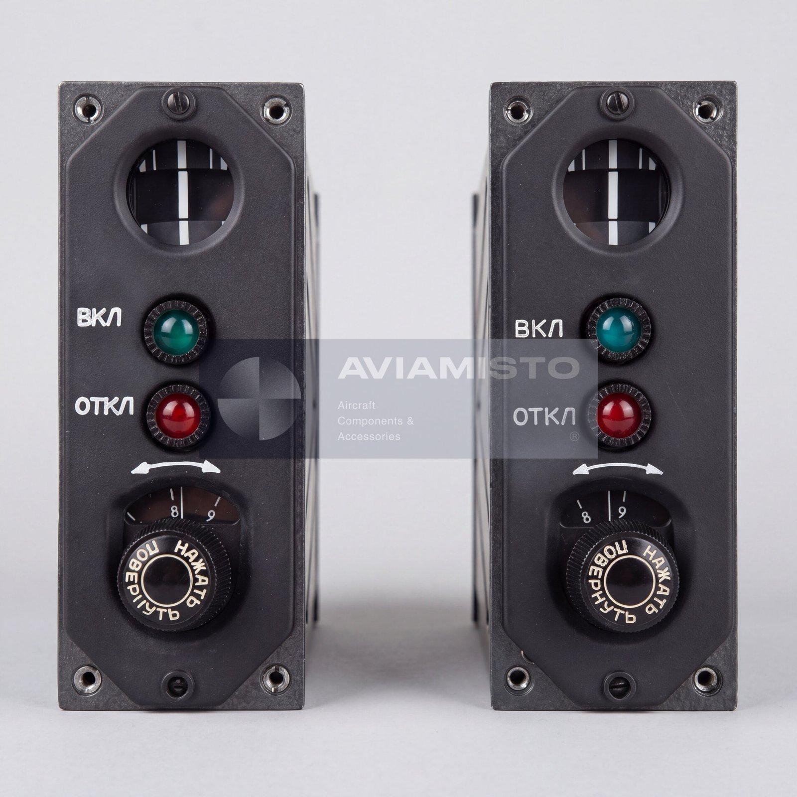
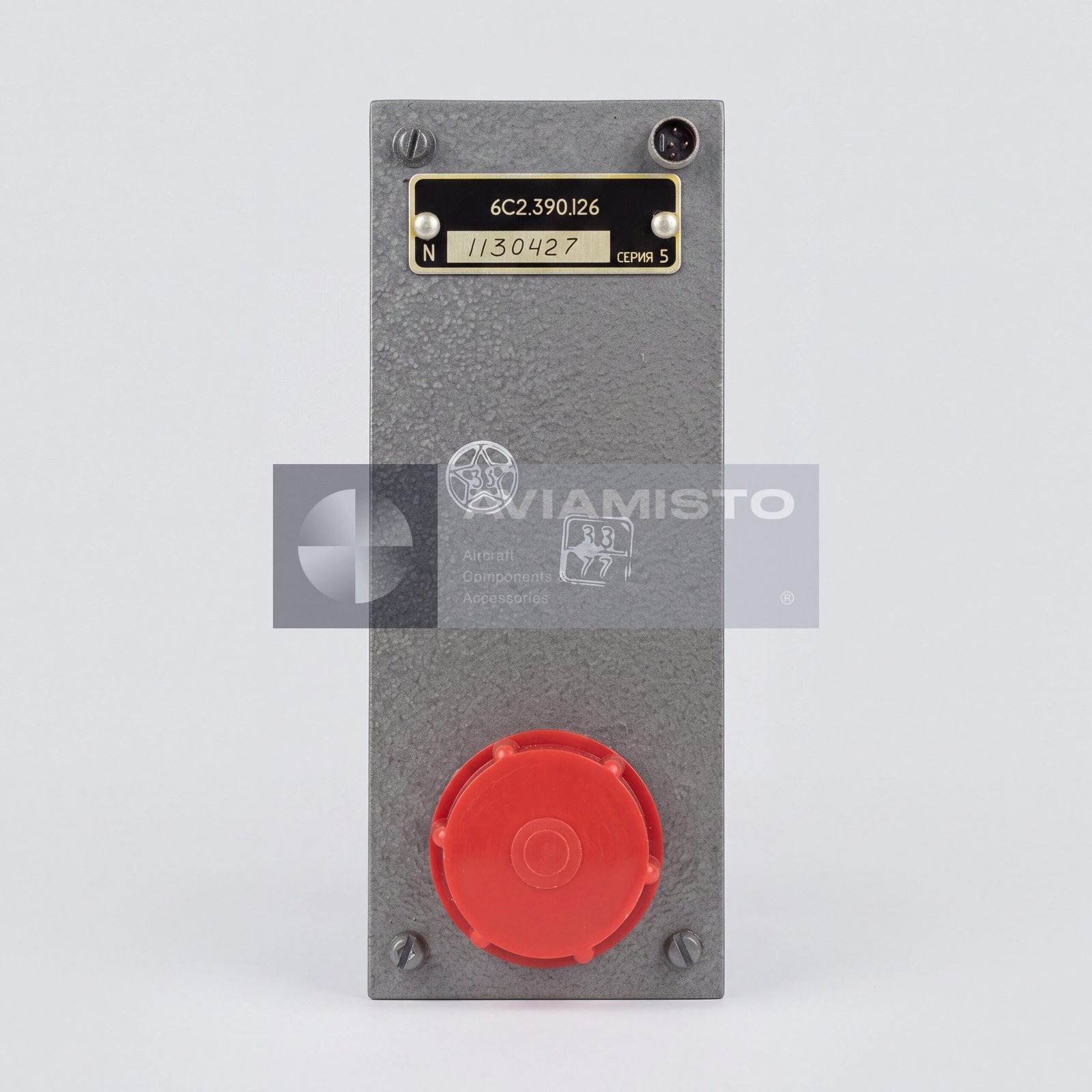
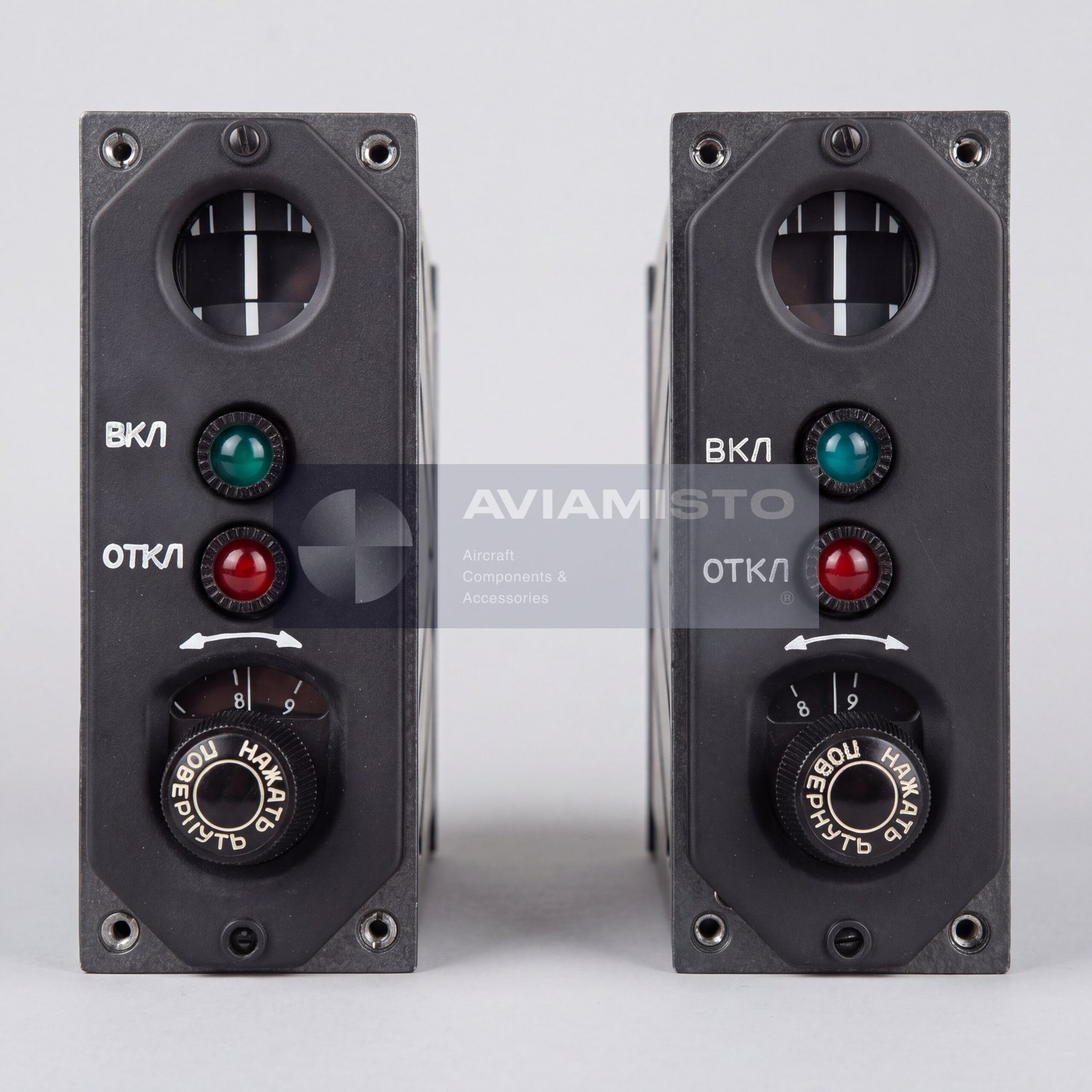
6S2.390.126-5 PU-126 Series 5 control panel
6S2.390.126-5 is an aircraft control panel known as PU-126 Series 5. The unit is intended for control, adjustment and indication functions within onboard automatic flight control, stabilization and navigation-related systems. The “-5” suffix identifies the fifth production series of the PU-126 panel. The panel is installed in the helicopter cockpit and operates as a crew interface for connected autopilot and flight control equipment.
Full descriptionCollapse description
PU-126 Series 5 in helicopter autopilot systems
The PU-126 Series 5 panel is used as part of unified helicopter autopilot and automatic control systems, including VUAP-1, SAU-V24-1 and PKV-252-1 flight control complexes where applicable by documentation. It supports mode selection, control signal generation and status indication for automatic stabilization and semi-automatic helicopter control. The panel itself is not an autopilot computer; it works together with control computers, switching units, sensors and related aircraft wiring.
Control channels of 6S2.390.126-5
The PU-126 panel is associated with control and manual adjustment of automatic flight trajectory parameters. In typical system layouts, PU-126 is linked with direction / yaw and altitude-related channels, while the adjacent 6S2.390.125 panel may be responsible for roll and pitch channels. Exact channel assignment must be confirmed by the aircraft wiring diagram and autopilot system documentation, because configurations may differ by helicopter type and modernization status.
Panel controls and indication
The 6S2.390.126-5 panel may include rotary adjustment knobs for smooth manual correction of angular position or altitude-related control signals, switches for selecting autopilot operating modes and illuminated indicators for channel engagement, readiness and failure annunciation. The panel forms control voltages through its internal switching and adjustment elements and sends these signals to the automatic control system units.
Cockpit installation and electrical interface
The PU-126 Series 5 is designed as a cockpit panel unit for installation on the central console, side console or other flight control area of the helicopter cockpit. The unit is connected to the aircraft system through a multi-pin connector on the rear side of the panel. Depending on aircraft wiring and illumination version, the panel may use DC power for main circuits and separate low-voltage or 28 V lighting circuits for indicator lamps and panel illumination.
Identification and ordering of 6S2.390.126-5
The product may be referenced as 6S2.390.126-5, 6С2.390.126-5, PU-126 Series 5 or ПУ-126 серия 5. For correct supply, it is useful to specify the aircraft type, installed autopilot or flight control complex, required series, connector type, illumination version, condition, documentation requirements and whether the unit must be supplied with passport, label or test certificate.
Technical details
- Product Type
- Aircraft control panel / autopilot control panel
- Designation
- 6S2.390.126-5
- Alternative Designations
- 6С2.390.126-5, PU-126 Series 5, ПУ-126 серия 5, control panel PU-126
- Function
- Control, switching, adjustment and indication for helicopter automatic control systems
- Purpose
- Cockpit interface for autopilot, stabilization and automatic flight control equipment
All specificationsCollapse specifications
- Application / Where Used
- Helicopter automatic flight control, stabilization and navigation-related systems
- Associated Systems
- VUAP-1, SAU-V24-1, PKV-252-1 where applicable by documentation
- Related Equipment
- 6S2.390.125 control panel and associated automatic control system units
- Compatible Aircraft
- Mi-8 / Mi-17 / Mi-171, Mi-24, Mi-26, Ka-32 and related helicopters where applicable by documentation
- System / Installation Area
- Helicopter cockpit autopilot / automatic control system panel area
- Installation Location
- Central console, side console or cockpit instrument panel according to aircraft documentation
- Typical Control Channels
- Direction / yaw and altitude channels, where applicable by system configuration
- Adjacent Panel Function
- 6S2.390.125 may be used for roll and pitch channels, depending on aircraft system layout
- DC Power Supply
- 27 V DC
- Permissible DC Voltage Range
- 24–29.4 V
- Panel / Indicator Lighting Supply
- 5.5 V or 28 V, depending on aircraft wiring and lamp configuration
- Current Consumption
- Not more than 0.5 A, excluding peak switching currents of automatic control system relays
- Output Signals
- Control voltages generated by panel switching and adjustment elements
- Controls
- Rotary adjustment knobs; mode switches; autopilot mode selection controls
- Indication
- Channel engagement, system readiness and failure indication where applicable
- Design
- Block-type cockpit panel unit
- Mounting Type
- Dzus-type or screw mounting depending on aircraft installation
- Connector Type
- Multi-pin rear connector, ShR / 2RM / 2RMD type where applicable
- Approximate Dimensions
- About 140 × 120 × 150 mm
- Weight
- Not more than 1.5 kg
- Operating Temperature Range
- −60 °C to +60 °C
- Vibration Resistance
- Designed for helicopter vibration environment up to 300 Hz according to supplied data
- Operating Mode
- Continuous
- Technical Documentation
- Product passport, aircraft installation documentation, wiring documentation and test documentation upon request
Payment & delivery
Orders ship from our hub in Dubai. Partner stock is first transferred to Dubai, then shipped to you.
Dubai stock: 100% before dispatch. Partner stock (Remote stock) and Pre-order: 50% advance payment to start the order and 50% before shipment from Dubai to you.
Availability, lead time, delivery cost and payment terms are confirmed for your order before payment.
Payment & delivery terms