


Control Panel
PU-26E
Price on request
Control Panel
Available on back-order
Description
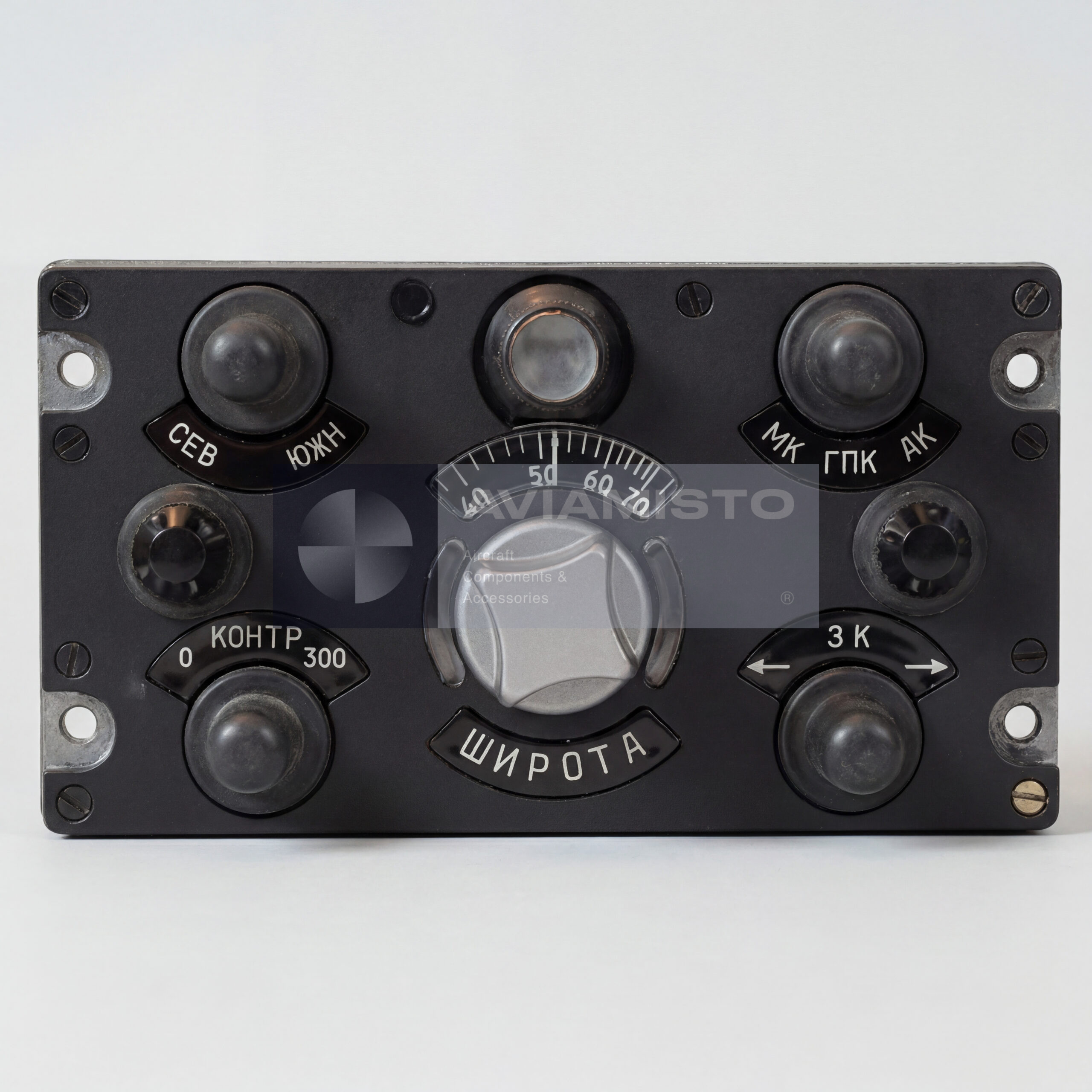
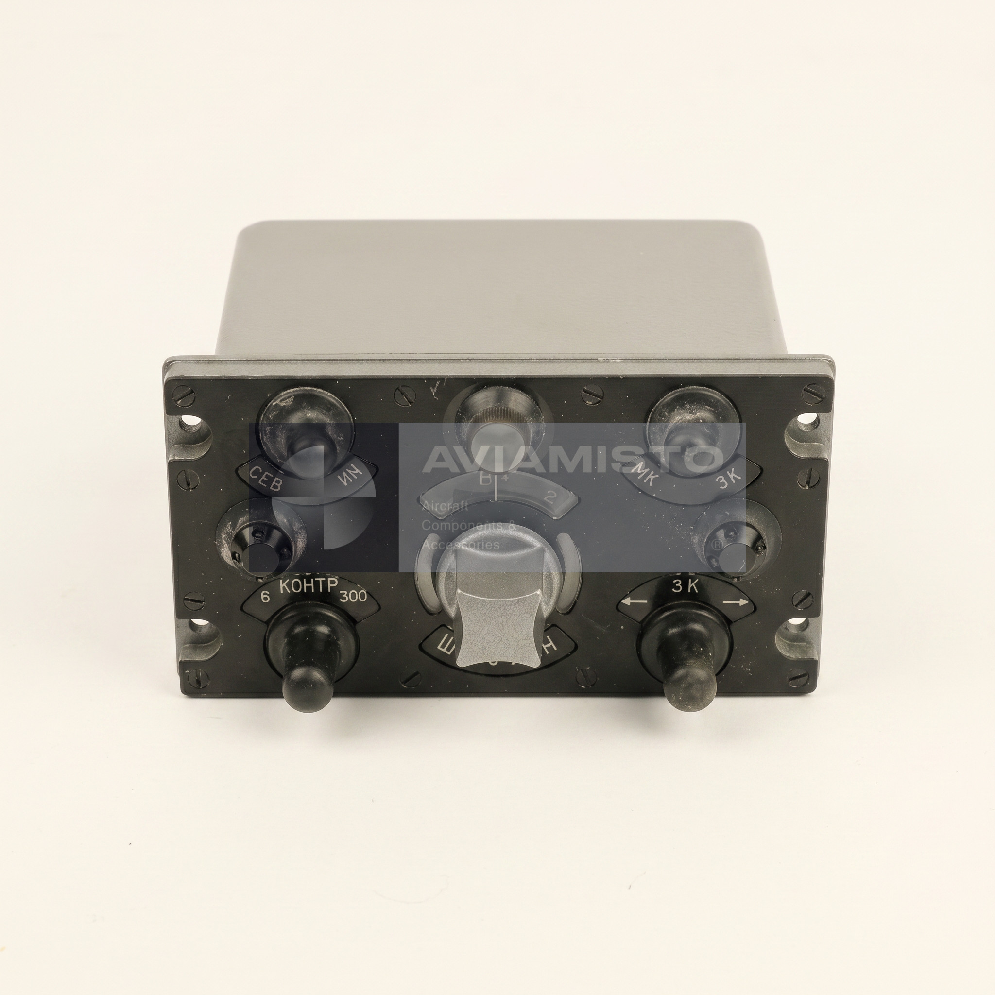
PU-26E control panel in the GMK-1AE system
The PU-26E is an aircraft control panel used with the GMK-1AE gyromagnetic heading system. It is installed in the cockpit and gives the crew access to the main operating controls of the heading system. The panel is used on helicopters such as Mi-8 variants and on some fixed-wing aircraft, including Yak-40-type installations, depending on equipment configuration. The “E” index identifies the export version of the equipment. In this version, the panel is matched with the GMK-1AE system and its related units, including the ID-3 induction detector, GA-6 gyro unit, KM-8 correction mechanism and AS-1 matching unit.
Mode selection through the PU-26E panel
The PU-26E allows the crew to switch the heading system between its main operating modes. In gyro heading mode, the system uses the gyro unit as the main heading reference. In magnetic correction mode, the gyro heading is corrected by the magnetic channel through the induction detector and correction mechanism. The panel provides fixed switching positions for these modes, so the crew can select the required logic for the flight conditions. Unlike some base versions of the PU-26 family, the PU-26E export configuration does not include the astro-correction mode.
Course synchronization using PU-26E
The panel includes a control for fast course synchronization. In magnetic correction mode, pressing the synchronization control activates the matching system and allows the heading system to remove the difference between the gyro heading and the magnetic channel. This function is used when the crew or maintenance personnel need the system to bring the gyro reference into agreement more quickly than during normal slow correction. The synchronization lamp on the front panel indicates the matching process and goes out when the system is ready for normal operation.
Latitude correction on the PU-26E panel
The PU-26E includes a latitude correction setting. This is needed because a free gyro has apparent drift caused by Earth rotation, and the correction depends on the geographic latitude of flight. The crew sets the current latitude by the scale and control on the panel. The correction signal is then used by the heading system to reduce gyro drift in operation. If the latitude setting is wrong, the gyro heading may drift faster than expected, especially during longer operation in gyro heading mode. For this reason, the latitude scale is not just an auxiliary marking; it is part of the heading system adjustment.
Adjustment elements inside the PU-26E
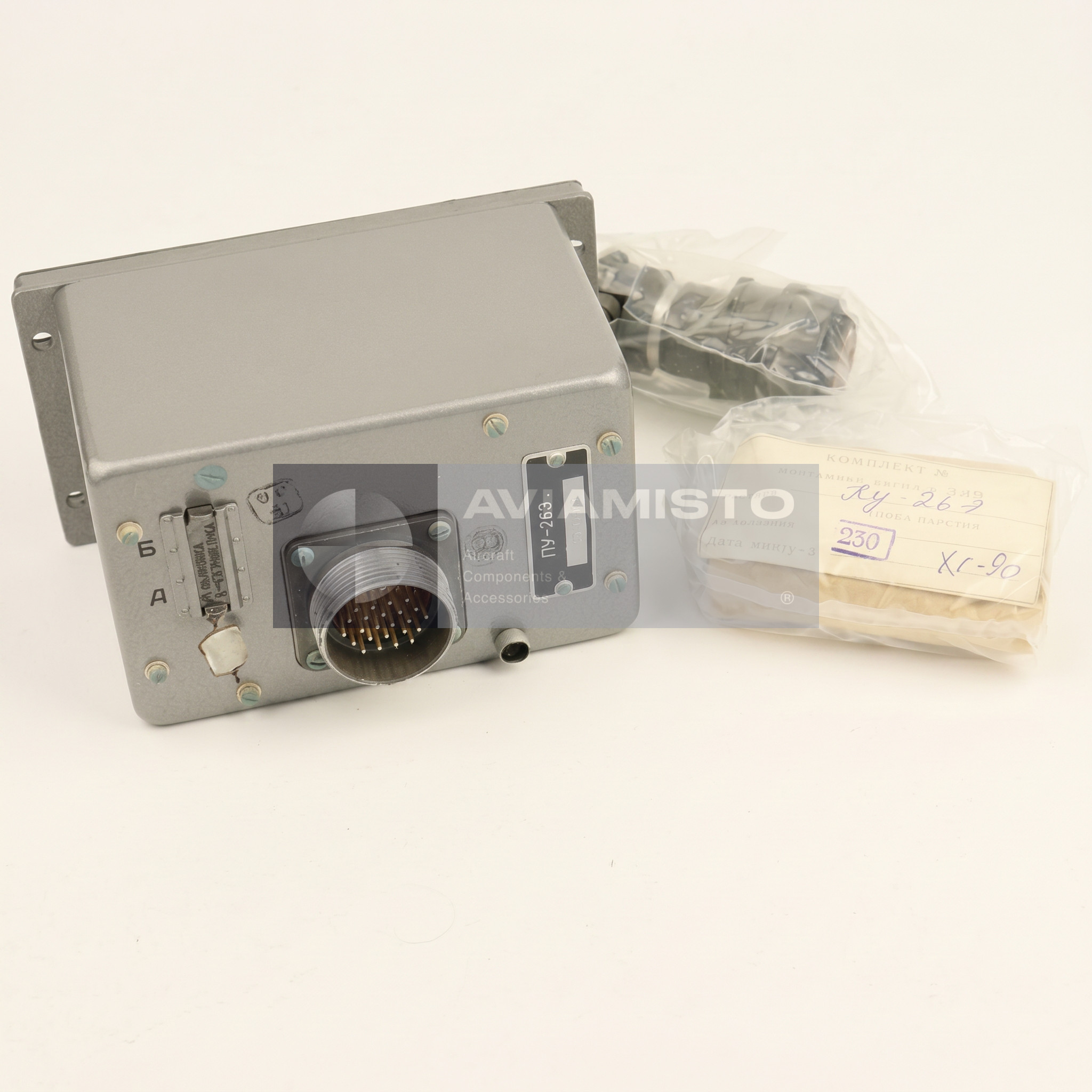
The PU-26E also contains adjustment elements used to compensate technical drift of the gyro system. These balancing potentiometers are located on the inner or rear side of the panel near the connector area, depending on execution. They are not controls for routine pilot use. They are adjusted during maintenance or system setup according to the technical documentation. Incorrect adjustment can affect drift compensation and heading stability, so these elements should be handled only as part of an approved GMK-1AE adjustment procedure.
Installation and cockpit use of PU-26E
The PU-26E is usually mounted on the right or central cockpit console, where the crew can reach the mode switch, synchronization button, latitude setting control and observe the readiness / synchronization indication. The panel is compact, but it is a functional control center for the heading system. During maintenance, technicians check the condition of the switches, lamp indication, panel lighting, connector, latitude setting mechanism and signal response in the connected system. The panel should be tested together with the AS-1, GA-6, ID-3 and KM-8, not only as a separate box.
Supply and identification of PU-26E
When ordering the PU-26E, it is important to specify the full designation and confirm that the requirement is for the export GMK-1AE version. The drawing or passport reference 6Zh3.624.002-2 should be used where applicable. Similar PU-26-family panels may differ in mode positions, markings, connector layout, lighting and compatibility with the installed heading system. For aircraft supply, the condition, passport, label, test status and compatibility with the aircraft wiring diagram should be checked before installation.
Details
Product Type: Aircraft heading system control panel
Designation: PU-26E
Associated System: GMK-1AE gyromagnetic heading system
Drawing / Passport Reference: 6Zh3.624.002-2
Function: Mode selection, fast course synchronization, latitude correction input and heading system control
Application / Where Used: Aircraft heading and navigation systems
System / Installation Area: Cockpit control panel, right or central pilot console depending on aircraft layout
Compatible Aircraft / Equipment: Mi-8 variants, Yak-40 and other aircraft equipped with GMK-1AE depending on configuration
Associated Components: ID-3 induction detector, GA-6 gyro unit, KM-8 correction mechanism, AS-1 matching unit
Main Mode Positions: GPK gyro heading mode and MK magnetic correction mode
Astro-Correction Mode: Not included in PU-26E export execution
Fast Synchronization Function: Activation of AS-1 matching unit by “Press for synchronization” control in MK mode
Synchronization Rate: Not less than 60°/s
Indication: Front-panel lamp for synchronization / readiness process
Latitude Correction Range: 0° to 90° North and South latitude
Latitude Setting Method: Manual setting by front-panel scale and knurled control
Gyro Drift Compensation Accuracy: Not worse than ±0.5° per hour, according to adjustment function data
DC Power Supply: 27 V DC ±10%
AC Power Supply: 36 V AC +5% / −10%
AC Frequency: 400 Hz ±2%
Current Consumption at 27 V DC: Not more than 0.5 A
Current Consumption at 36 V AC: Not more than 0.1 A
Panel Lighting: Built-in red flood lighting; lamp voltage depends on production series
Connector Type: ShR-type rear plug connector, usually 20- or 24-pin depending on execution
Dimensions: Approximately 145 × 63 × 165 mm
Weight: Approximately 1.1 kg
Associated System Weight: GMK-1AE system approximately 11.5 kg
Operating Temperature Range: −60 to +60 °C
Vibration Resistance: 10–80 Hz, acceleration up to 1.5 g
Technical Documentation: Product passport, GMK-1AE technical documentation, wiring diagrams and aircraft maintenance documentation as applicable
Payment & delivery
All shipments are carried out from our international warehouse in Dubai (UAE), as well as from our partners’ remote warehouses.
In Stock — items available in stock at the Dubai warehouse are dispatched within 5–10 business days after receiving 100% prepayment.
Remote Stock — items available at our partners’ remote warehouses are supplied within an average of 30–45 business days after receiving 100% prepayment.
Pre-Order — made-to-order products are manufactured and delivered within an average of 45–60 business days. Payment terms: 50% advance payment to start production, with the remaining 50% paid before dispatch from the Dubai warehouse after full readiness for shipment.
Returns & Changes (Restocking Fee)
For selected items, a RESTOCKING FEE of 10% may apply in case of return, order cancellation, or changes to the order specifications. This condition applies only to certain products and is confirmed at the order approval stage.
Warranty
All products are covered by a standard 6-month warranty.
Extended warranty is available upon request and is agreed individually; it may affect the final product price.
- Description
- Details
- Payment & delivery
PU-26E control panel in the GMK-1AE system
The PU-26E is an aircraft control panel used with the GMK-1AE gyromagnetic heading system. It is installed in the cockpit and gives the crew access to the main operating controls of the heading system. The panel is used on helicopters such as Mi-8 variants and on some fixed-wing aircraft, including Yak-40-type installations, depending on equipment configuration. The “E” index identifies the export version of the equipment. In this version, the panel is matched with the GMK-1AE system and its related units, including the ID-3 induction detector, GA-6 gyro unit, KM-8 correction mechanism and AS-1 matching unit.
Mode selection through the PU-26E panel
The PU-26E allows the crew to switch the heading system between its main operating modes. In gyro heading mode, the system uses the gyro unit as the main heading reference. In magnetic correction mode, the gyro heading is corrected by the magnetic channel through the induction detector and correction mechanism. The panel provides fixed switching positions for these modes, so the crew can select the required logic for the flight conditions. Unlike some base versions of the PU-26 family, the PU-26E export configuration does not include the astro-correction mode.
Course synchronization using PU-26E
The panel includes a control for fast course synchronization. In magnetic correction mode, pressing the synchronization control activates the matching system and allows the heading system to remove the difference between the gyro heading and the magnetic channel. This function is used when the crew or maintenance personnel need the system to bring the gyro reference into agreement more quickly than during normal slow correction. The synchronization lamp on the front panel indicates the matching process and goes out when the system is ready for normal operation.
Latitude correction on the PU-26E panel
The PU-26E includes a latitude correction setting. This is needed because a free gyro has apparent drift caused by Earth rotation, and the correction depends on the geographic latitude of flight. The crew sets the current latitude by the scale and control on the panel. The correction signal is then used by the heading system to reduce gyro drift in operation. If the latitude setting is wrong, the gyro heading may drift faster than expected, especially during longer operation in gyro heading mode. For this reason, the latitude scale is not just an auxiliary marking; it is part of the heading system adjustment.
Adjustment elements inside the PU-26E
The PU-26E also contains adjustment elements used to compensate technical drift of the gyro system. These balancing potentiometers are located on the inner or rear side of the panel near the connector area, depending on execution. They are not controls for routine pilot use. They are adjusted during maintenance or system setup according to the technical documentation. Incorrect adjustment can affect drift compensation and heading stability, so these elements should be handled only as part of an approved GMK-1AE adjustment procedure.
Installation and cockpit use of PU-26E
The PU-26E is usually mounted on the right or central cockpit console, where the crew can reach the mode switch, synchronization button, latitude setting control and observe the readiness / synchronization indication. The panel is compact, but it is a functional control center for the heading system. During maintenance, technicians check the condition of the switches, lamp indication, panel lighting, connector, latitude setting mechanism and signal response in the connected system. The panel should be tested together with the AS-1, GA-6, ID-3 and KM-8, not only as a separate box.
Supply and identification of PU-26E
When ordering the PU-26E, it is important to specify the full designation and confirm that the requirement is for the export GMK-1AE version. The drawing or passport reference 6Zh3.624.002-2 should be used where applicable. Similar PU-26-family panels may differ in mode positions, markings, connector layout, lighting and compatibility with the installed heading system. For aircraft supply, the condition, passport, label, test status and compatibility with the aircraft wiring diagram should be checked before installation.
Product Type: Aircraft heading system control panel
Designation: PU-26E
Associated System: GMK-1AE gyromagnetic heading system
Drawing / Passport Reference: 6Zh3.624.002-2
Function: Mode selection, fast course synchronization, latitude correction input and heading system control
Application / Where Used: Aircraft heading and navigation systems
System / Installation Area: Cockpit control panel, right or central pilot console depending on aircraft layout
Compatible Aircraft / Equipment: Mi-8 variants, Yak-40 and other aircraft equipped with GMK-1AE depending on configuration
Associated Components: ID-3 induction detector, GA-6 gyro unit, KM-8 correction mechanism, AS-1 matching unit
Main Mode Positions: GPK gyro heading mode and MK magnetic correction mode
Astro-Correction Mode: Not included in PU-26E export execution
Fast Synchronization Function: Activation of AS-1 matching unit by “Press for synchronization” control in MK mode
Synchronization Rate: Not less than 60°/s
Indication: Front-panel lamp for synchronization / readiness process
Latitude Correction Range: 0° to 90° North and South latitude
Latitude Setting Method: Manual setting by front-panel scale and knurled control
Gyro Drift Compensation Accuracy: Not worse than ±0.5° per hour, according to adjustment function data
DC Power Supply: 27 V DC ±10%
AC Power Supply: 36 V AC +5% / −10%
AC Frequency: 400 Hz ±2%
Current Consumption at 27 V DC: Not more than 0.5 A
Current Consumption at 36 V AC: Not more than 0.1 A
Panel Lighting: Built-in red flood lighting; lamp voltage depends on production series
Connector Type: ShR-type rear plug connector, usually 20- or 24-pin depending on execution
Dimensions: Approximately 145 × 63 × 165 mm
Weight: Approximately 1.1 kg
Associated System Weight: GMK-1AE system approximately 11.5 kg
Operating Temperature Range: −60 to +60 °C
Vibration Resistance: 10–80 Hz, acceleration up to 1.5 g
Technical Documentation: Product passport, GMK-1AE technical documentation, wiring diagrams and aircraft maintenance documentation as applicable
All shipments are carried out from our international warehouse in Dubai (UAE), as well as from our partners’ remote warehouses.
In Stock — items available in stock at the Dubai warehouse are dispatched within 5–10 business days after receiving 100% prepayment.
Remote Stock — items available at our partners’ remote warehouses are supplied within an average of 30–45 business days after receiving 100% prepayment.
Pre-Order — made-to-order products are manufactured and delivered within an average of 45–60 business days. Payment terms: 50% advance payment to start production, with the remaining 50% paid before dispatch from the Dubai warehouse after full readiness for shipment.
Returns & Changes (Restocking Fee)
For selected items, a RESTOCKING FEE of 10% may apply in case of return, order cancellation, or changes to the order specifications. This condition applies only to certain products and is confirmed at the order approval stage.
Warranty
All products are covered by a standard 6-month warranty.
Extended warranty is available upon request and is agreed individually; it may affect the final product price.