


Communication Unit for GMK-1
BS-1
Price on request
Communication Unit for GMK-1
Available on back-order
Description
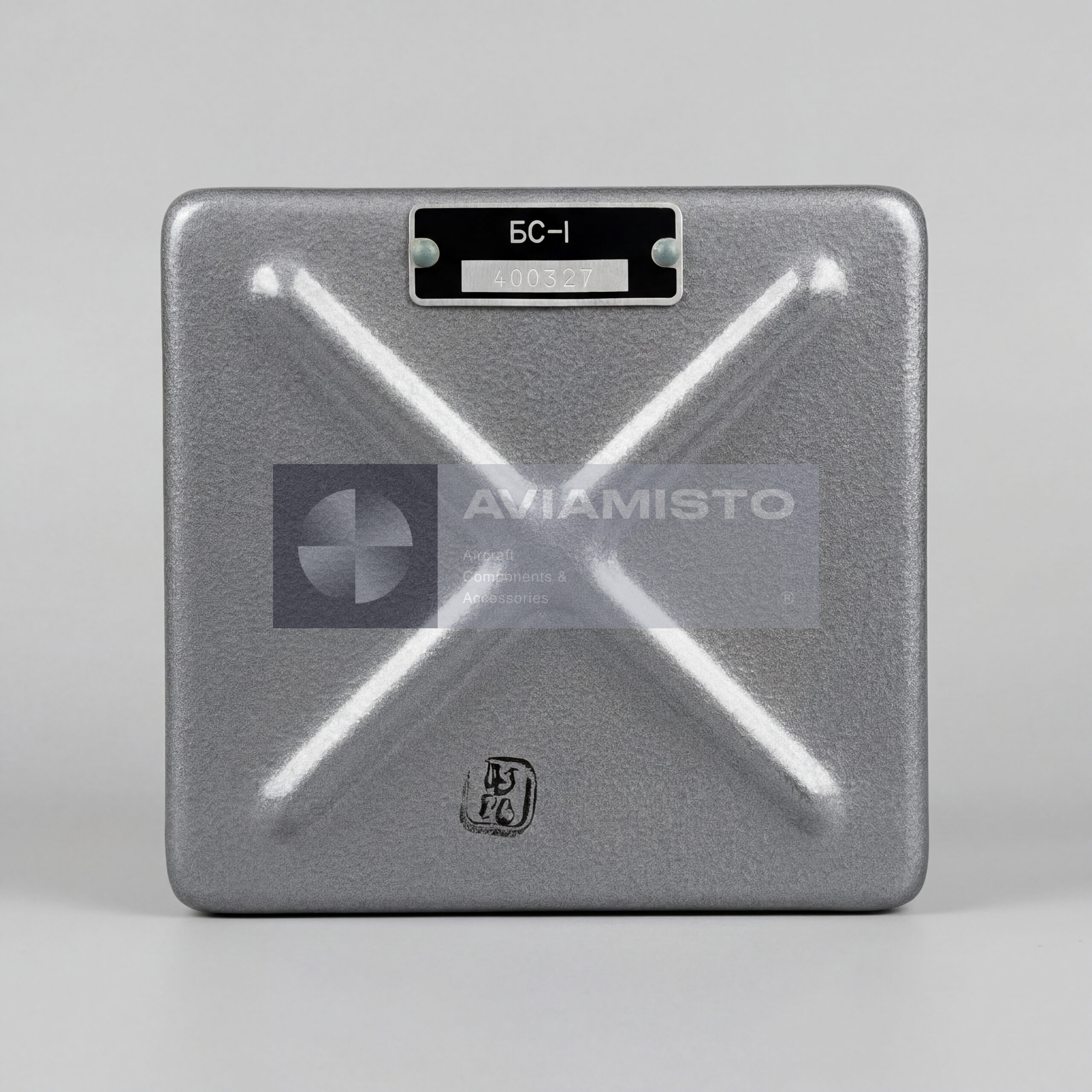
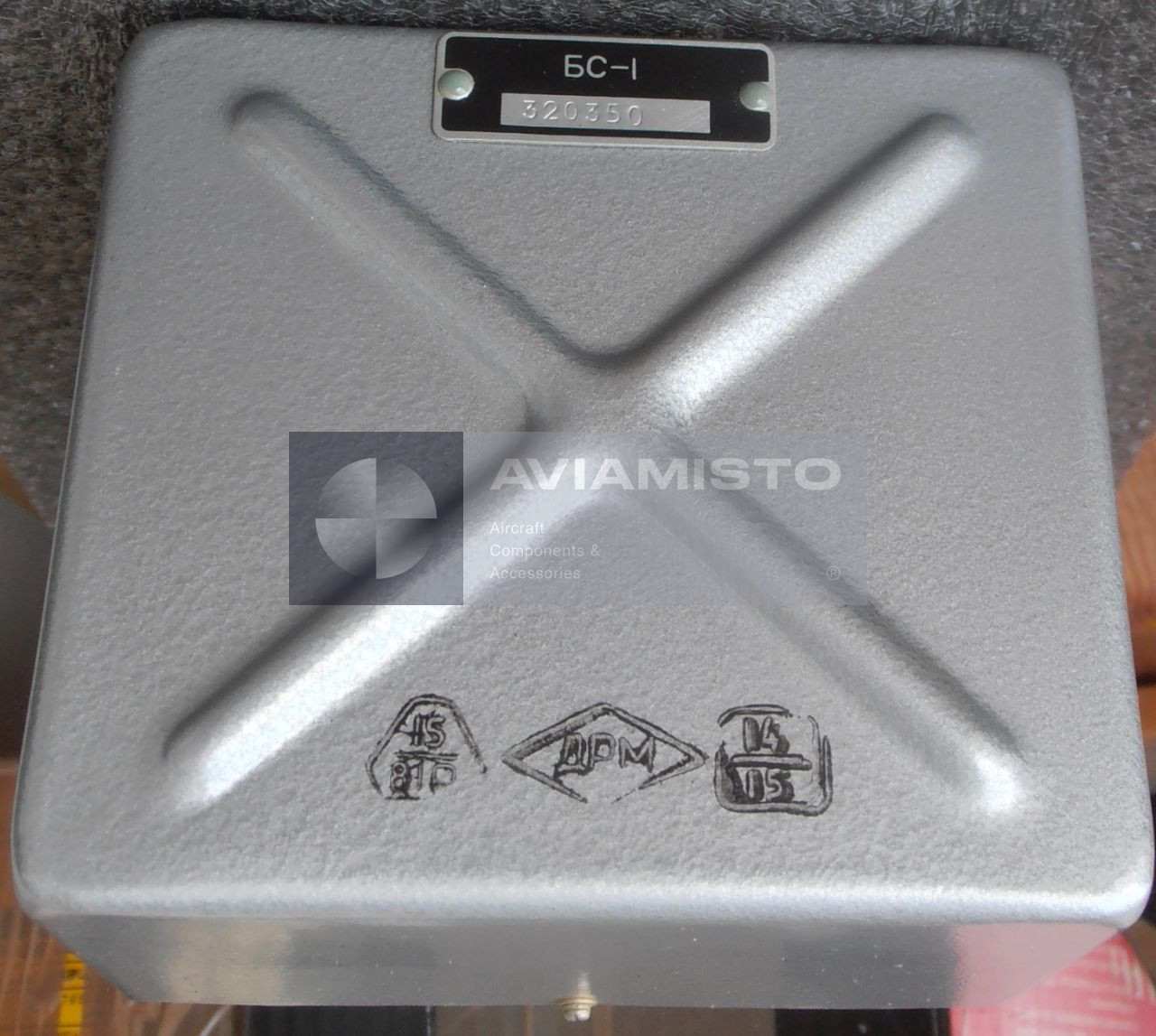
BS-1 unit in the GMK-1 heading system
The BS-1 is an aircraft communication and signal-interface unit used as part of the GMK-1 heading system, including GMK-1A, GMK-1G and GMK-1GE versions. The unit is known by drawing number 6Zh3.619.002 and works inside the heading reference equipment rather than as an independent navigation instrument. Its role is to connect, switch and route signals between the main GMK-1 components, so that heading data from the gyro and correction circuits can be used by cockpit indicators and other onboard consumers.
Signal routing through the BS-1 block
In the GMK-1 system, the BS-1 handles the electrical connection between units that generate, correct and display heading information. It helps route heading signals from the gyro unit to indicators such as UGR-4UK, and also to external users when the aircraft configuration requires it. These users may include autopilot channels or navigation equipment that need heading data for stabilization, course holding or related functions. The block is therefore part of the signal chain that keeps the heading system useful beyond the cockpit indicator alone.
BS-1 with GMK-1 system components
The BS-1 normally operates together with the main GMK-1 equipment group: the ID-3 induction detector, GA-6 gyro unit, KM-8 correction mechanism, AS-1 matching unit and PU-26 or PU-27 control panel. Each of these units has its own task, but they need stable electrical coordination to work as one system. The BS-1 supports that coordination by switching and matching the required circuits. When diagnosing heading system faults, this block should be considered together with the connected units, wiring and aircraft power supply, not as an isolated box.
Heading data transfer and autopilot signal
One of the functions associated with the BS-1 is transfer of angular heading information through synchro-type circuits. In the heading system, the block may also participate in forming the Δψ signal, which represents the difference between the selected course and the current aircraft heading. This signal can be used by the autopilot or stabilization equipment, depending on aircraft installation. Because the signal is related to course control, small transmission errors matter. The unit must maintain correct signal continuity and switching accuracy within the limits specified for the GMK-1 system.
Operating modes supported by BS-1
The BS-1 is involved in switching circuits used in different GMK-1 operating modes, including magnetic correction and gyro-compass operation. In magnetic correction mode, the system works with data from the induction detector and correction circuits. In gyro mode, the system relies on the gyro reference and related control logic. The exact switching behavior depends on the GMK-1 modification and aircraft wiring diagram. For replacement or troubleshooting, the unit should be checked against the specific system version installed on the aircraft.
Aircraft application of the BS-1 unit
The GMK-1 heading system was used on various Soviet and Russian aircraft and helicopters, including platforms such as Mi-8 and Yak-40, depending on modification and installed avionics package. The BS-1 unit belongs to this heading system and is usually required when maintaining, repairing or restoring the complete GMK-1 installation. Before supply, it is important to confirm the exact system version, drawing number, connector type and documentation. Similar-looking units from related heading systems may not be interchangeable without verification through the aircraft parts catalog and wiring documentation.
Details
Product Type: Aircraft communication / signal-interface unit
Designation: BS-1
Drawing Number: 6Zh3.619.002
Associated System: GMK-1 aircraft heading system
Applicable System Versions: GMK-1A, GMK-1G, GMK-1GE
Function: Signal switching, matching and transfer within the heading system
Application / Where Used: Aircraft heading reference and navigation systems
System / Installation Area: Avionics equipment bay or heading system equipment rack, depending on aircraft layout
Main Signal Function: Transfer of heading data from the gyro unit to indicators and external consumers
Associated Indicator: UGR-4UK heading indicator, depending on system configuration
Associated System Components: ID-3 induction detector, GA-6 gyro unit, KM-8 correction mechanism, AS-1 matching unit, PU-26 / PU-27 control panel
External Consumers: Autopilot and navigation equipment, depending on aircraft configuration
Δψ Signal Function: Course error signal between selected course and current aircraft heading
Supported Modes: Magnetic correction mode and gyro-compass mode, depending on GMK-1 version
AC Power Supply: 36 V ±5%, 400 Hz ±2%, single-phase AC
DC Power Supply: 27 V nominal DC, operating range 24–29.4 V
Signal Transmission Error: Approximately ±0.2° to ±0.5° in synchro heading transmission circuits, depending on system conditions
Operating Temperature Range: −60 to +60 °C
Maximum Operating Altitude: Up to 20,000 m
Weight: Approximately 1.3–1.5 kg
Approximate Dimensions: 180 × 120 × 110 mm
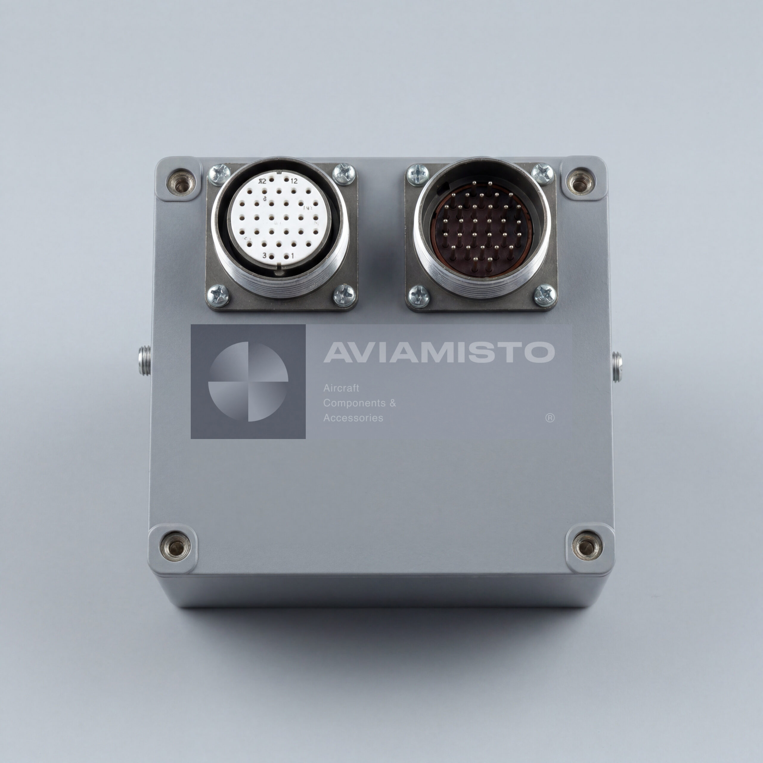
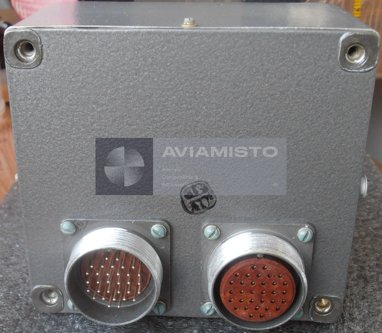
Connection Type: Aircraft plug or blade-type connector depending on execution
Technical Documentation: GMK-1 system documentation, aircraft wiring diagrams, product passport / label when available
Payment & delivery
All shipments are carried out from our international warehouse in Dubai (UAE), as well as from our partners’ remote warehouses.
In Stock — items available in stock at the Dubai warehouse are dispatched within 5–10 business days after receiving 100% prepayment.
Remote Stock — items available at our partners’ remote warehouses are supplied within an average of 30–45 business days after receiving 100% prepayment.
Pre-Order — made-to-order products are manufactured and delivered within an average of 45–60 business days. Payment terms: 50% advance payment to start production, with the remaining 50% paid before dispatch from the Dubai warehouse after full readiness for shipment.
Returns & Changes (Restocking Fee)
For selected items, a RESTOCKING FEE of 10% may apply in case of return, order cancellation, or changes to the order specifications. This condition applies only to certain products and is confirmed at the order approval stage.
Warranty
All products are covered by a standard 6-month warranty.
Extended warranty is available upon request and is agreed individually; it may affect the final product price.
- Description
- Details
- Payment & delivery
BS-1 unit in the GMK-1 heading system
The BS-1 is an aircraft communication and signal-interface unit used as part of the GMK-1 heading system, including GMK-1A, GMK-1G and GMK-1GE versions. The unit is known by drawing number 6Zh3.619.002 and works inside the heading reference equipment rather than as an independent navigation instrument. Its role is to connect, switch and route signals between the main GMK-1 components, so that heading data from the gyro and correction circuits can be used by cockpit indicators and other onboard consumers.
Signal routing through the BS-1 block
In the GMK-1 system, the BS-1 handles the electrical connection between units that generate, correct and display heading information. It helps route heading signals from the gyro unit to indicators such as UGR-4UK, and also to external users when the aircraft configuration requires it. These users may include autopilot channels or navigation equipment that need heading data for stabilization, course holding or related functions. The block is therefore part of the signal chain that keeps the heading system useful beyond the cockpit indicator alone.
BS-1 with GMK-1 system components
The BS-1 normally operates together with the main GMK-1 equipment group: the ID-3 induction detector, GA-6 gyro unit, KM-8 correction mechanism, AS-1 matching unit and PU-26 or PU-27 control panel. Each of these units has its own task, but they need stable electrical coordination to work as one system. The BS-1 supports that coordination by switching and matching the required circuits. When diagnosing heading system faults, this block should be considered together with the connected units, wiring and aircraft power supply, not as an isolated box.
Heading data transfer and autopilot signal
One of the functions associated with the BS-1 is transfer of angular heading information through synchro-type circuits. In the heading system, the block may also participate in forming the Δψ signal, which represents the difference between the selected course and the current aircraft heading. This signal can be used by the autopilot or stabilization equipment, depending on aircraft installation. Because the signal is related to course control, small transmission errors matter. The unit must maintain correct signal continuity and switching accuracy within the limits specified for the GMK-1 system.
Operating modes supported by BS-1
The BS-1 is involved in switching circuits used in different GMK-1 operating modes, including magnetic correction and gyro-compass operation. In magnetic correction mode, the system works with data from the induction detector and correction circuits. In gyro mode, the system relies on the gyro reference and related control logic. The exact switching behavior depends on the GMK-1 modification and aircraft wiring diagram. For replacement or troubleshooting, the unit should be checked against the specific system version installed on the aircraft.
Aircraft application of the BS-1 unit
The GMK-1 heading system was used on various Soviet and Russian aircraft and helicopters, including platforms such as Mi-8 and Yak-40, depending on modification and installed avionics package. The BS-1 unit belongs to this heading system and is usually required when maintaining, repairing or restoring the complete GMK-1 installation. Before supply, it is important to confirm the exact system version, drawing number, connector type and documentation. Similar-looking units from related heading systems may not be interchangeable without verification through the aircraft parts catalog and wiring documentation.
Product Type: Aircraft communication / signal-interface unit
Designation: BS-1
Drawing Number: 6Zh3.619.002
Associated System: GMK-1 aircraft heading system
Applicable System Versions: GMK-1A, GMK-1G, GMK-1GE
Function: Signal switching, matching and transfer within the heading system
Application / Where Used: Aircraft heading reference and navigation systems
System / Installation Area: Avionics equipment bay or heading system equipment rack, depending on aircraft layout
Main Signal Function: Transfer of heading data from the gyro unit to indicators and external consumers
Associated Indicator: UGR-4UK heading indicator, depending on system configuration
Associated System Components: ID-3 induction detector, GA-6 gyro unit, KM-8 correction mechanism, AS-1 matching unit, PU-26 / PU-27 control panel
External Consumers: Autopilot and navigation equipment, depending on aircraft configuration
Δψ Signal Function: Course error signal between selected course and current aircraft heading
Supported Modes: Magnetic correction mode and gyro-compass mode, depending on GMK-1 version
AC Power Supply: 36 V ±5%, 400 Hz ±2%, single-phase AC
DC Power Supply: 27 V nominal DC, operating range 24–29.4 V
Signal Transmission Error: Approximately ±0.2° to ±0.5° in synchro heading transmission circuits, depending on system conditions
Operating Temperature Range: −60 to +60 °C
Maximum Operating Altitude: Up to 20,000 m
Weight: Approximately 1.3–1.5 kg
Approximate Dimensions: 180 × 120 × 110 mm
Connection Type: Aircraft plug or blade-type connector depending on execution
Technical Documentation: GMK-1 system documentation, aircraft wiring diagrams, product passport / label when available
All shipments are carried out from our international warehouse in Dubai (UAE), as well as from our partners’ remote warehouses.
In Stock — items available in stock at the Dubai warehouse are dispatched within 5–10 business days after receiving 100% prepayment.
Remote Stock — items available at our partners’ remote warehouses are supplied within an average of 30–45 business days after receiving 100% prepayment.
Pre-Order — made-to-order products are manufactured and delivered within an average of 45–60 business days. Payment terms: 50% advance payment to start production, with the remaining 50% paid before dispatch from the Dubai warehouse after full readiness for shipment.
Returns & Changes (Restocking Fee)
For selected items, a RESTOCKING FEE of 10% may apply in case of return, order cancellation, or changes to the order specifications. This condition applies only to certain products and is confirmed at the order approval stage.
Warranty
All products are covered by a standard 6-month warranty.
Extended warranty is available upon request and is agreed individually; it may affect the final product price.