
GA 111N
hydraulic lock
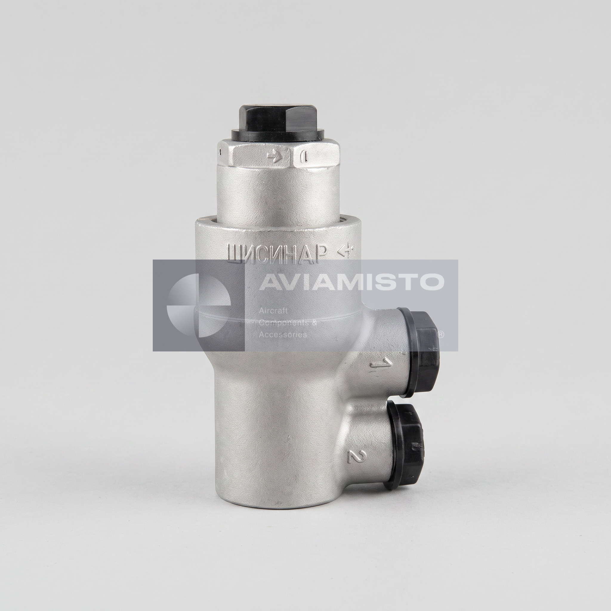

Description
Purpose of GA 111N in an onboard system
GA 111N is a Hydraulic lock for NGZh fluid with thermal relief valve that locks the working medium in one side of a power cylinder when pressure is absent from the pressure and control lines, while its thermal relief stage limits pressure rise caused by heating of the trapped fluid. Its published working medium is NGZh-4 or NGZh-5U hydraulic fluid. The unit is a functional element of a defined line, not an independent pressure source. Correct selection depends on more than the body marking: connection geometry, working medium, flow direction, pressure class and the exact execution must all agree with the installation. This page was rebuilt from the specialist Uralprom catalogue and cross-checked against available aviation documentation; specifications were not borrowed from visually similar products. This check is particularly important for legacy designations that may appear with a space, a hyphen or no separator in paper passports, stock databases and export lists. Search forms help identify the item, but they do not change its physical execution.
Full descriptionCollapse description
How the GA 111N unit operates
Control pressure opens the internal passage to the cylinder. When the control command is removed, the lock retains the working medium in the isolated chamber and helps hold the connected actuator in position. The built-in thermal relief valve performs a separate protective task by relieving a trapped volume if thermal expansion increases pressure. This function does not make the unit a directional distributor or a continuous pressure regulator. Reliable operation depends on a clean working medium, serviceable seating surfaces and seals, undamaged threads and correct body orientation. If a connected actuator does not hold position or line pressure falls, maintenance personnel normally inspect not only GA 111N, but also the pump, filter, pipelines, fittings, power cylinder and adjacent valves in the same circuit.
Published operating data and connections
Published catalogue data gives a nominal pressure of 21 MPa / 210 kgf/cm², a nominal flow capacity of 15 L/min, hydraulic resistance of not more than 0.3 MPa / 3 kgf/cm² at nominal flow, an operating temperature range of −60 °C to +100 °C, and the following opening parameter: thermal relief valve opens at 26 MPa / 260 kgf/cm². Mass: not more than 0.31 kg. Connections: D1 M12×1.5; D2 M10×1.5; D3 M12×1.5. These values help distinguish the unit from similar catalogue positions and verify the mounting location. Exact aircraft applicability for the N execution was not independently established in the reviewed public documentation. Before installation, the figures should be checked against the product passport, current technical specification and documentation for the particular aircraft. If the supplied unit or its passport records a different execution, the documentation accompanying that unit takes precedence.
Installing GA 111N and confirming aircraft applicability
Installation area: Compatible NGZh-fluid power-cylinder pressure and control lines. No exact aircraft or helicopter type for this execution was independently confirmed in the reviewed public documentation. Applicability is therefore not inferred from appearance or from a neighbouring family designation; it must be established from the IPC, maintenance manual, system diagram or product passport. Routine maintenance normally includes checking the marking, flow direction, connection tightness, body condition and contamination. Selection by diameter or photograph alone is unsafe because a similar body may be produced for another medium, thread, flow capacity or setting. Pumps, cylinders and distributors connected in the same circuit are associated components, but they perform different tasks and must not be presented as interchangeable with this unit. Before installation, the unit should be examined for corrosion, damaged threads and evidence of unsuitable storage; after connection, the approved leakage and functional checks should be completed. Test pressure, preservation method and depreservation procedure cannot be assigned from a general family description and must come from the passport or approved repair documentation. If the nameplate and accompanying documents disagree, installation should stop until the execution is clarified.
Designations, documents and related products
The primary English catalogue designation is GA 111N. Procurement lists, export records and Cyrillic documentation may also use: GA-111N; GA111N; ГА 111Н; ГА-111Н; ГА111Н. These forms are included to identify one product, not to create separate items. An enquiry should state the complete marking, system type, working medium, mounting position, required condition, delivery set and whether a passport or test record is needed. The control valves and hydraulic units category also contains related positions: GA 111, GA 111A, OK 10A, OK 18A. They belong to the same commercial and functional group, but an internal link does not establish compatibility or interchangeability. The final selection must follow the illustrated parts catalogue and approved aircraft documentation. Serial number, production date and actual delivery set are confirmed separately for the specific supplied unit.
Technical details
- Product Type
- Hydraulic lock for NGZh fluid with thermal relief valve
- Designation
- GA 111N
- Russian Designation
- ГА 111Н
- Alternative Designations
- GA-111N; GA111N; ГА 111Н; ГА-111Н; ГА111Н
- Function
- Locking the working medium in a power-cylinder chamber when control pressure is absent
All specificationsCollapse specifications
- Working Medium
- NGZh-4 or NGZh-5U hydraulic fluid
- Nominal Pressure
- 21 MPa / 210 kgf/cm²
- Nominal Flow Capacity
- 15 L/min
- Hydraulic Resistance
- not more than 0.3 MPa / 3 kgf/cm² at nominal flow
- Operating Temperature
- −60 °C to +100 °C
- Opening Parameter / Thermal Relief
- thermal relief valve opens at 26 MPa / 260 kgf/cm²
- Connection Data
- D1 M12×1.5; D2 M10×1.5; D3 M12×1.5
- Mass
- not more than 0.31 kg
- Aircraft Type
- Not confirmed in the reviewed public documentation
- System / Installation Area
- Compatible NGZh-fluid power-cylinder pressure and control lines
- Nearest Associated Components
- Pump, filter, pipeline, distributor and power cylinder in the applicable circuit; exact Part Numbers must be checked in aircraft documentation
- Interchangeability
- Not established; related positions are not automatic substitutes
- Technical Documentation
- Product passport, technical specification, system diagram and illustrated parts catalogue when available
- Technical Data Source
- Specialist Uralprom catalogue; ambiguous rows are identified and require passport verification
Payment & delivery
Orders ship from our hub in Dubai. Partner stock is first transferred to Dubai, then shipped to you.
Dubai stock: 100% before dispatch. Partner stock (Remote stock) and Pre-order: 50% advance payment to start the order and 50% before shipment from Dubai to you.
Availability, lead time, delivery cost and payment terms are confirmed for your order before payment.
Payment & delivery terms