
A-034-4-18
Altitude indicator


Description
A-034-4-18 pointer indicator for radio-altitude information
A-034-4-18 is a cockpit pointer indicator intended to present radio-altitude information supplied by compatible onboard radio-altimeter equipment. The instrument gives the crew a direct visual reading of the aircraft's true height above the terrain or water beneath it. It is a display and warning interface rather than an independent measuring device: the transmitting and receiving equipment forms the altitude signal, while the indicator converts that signal into pointer movement on the cockpit scale.
The unit belongs to the A-034-4 family of indicators, which was produced in several executions for different radio-altimeter sets and cockpit configurations. Those executions can look similar from the front but may differ in scale range, illumination, connector arrangement, electrical interface and warning logic. For this reason, the complete designation A-034-4-18 must be checked against the equipment list, wiring diagram and passport of the aircraft before installation or replacement.
Full descriptionCollapse description
Reading the 0–1500 m scale of A-034-4-18
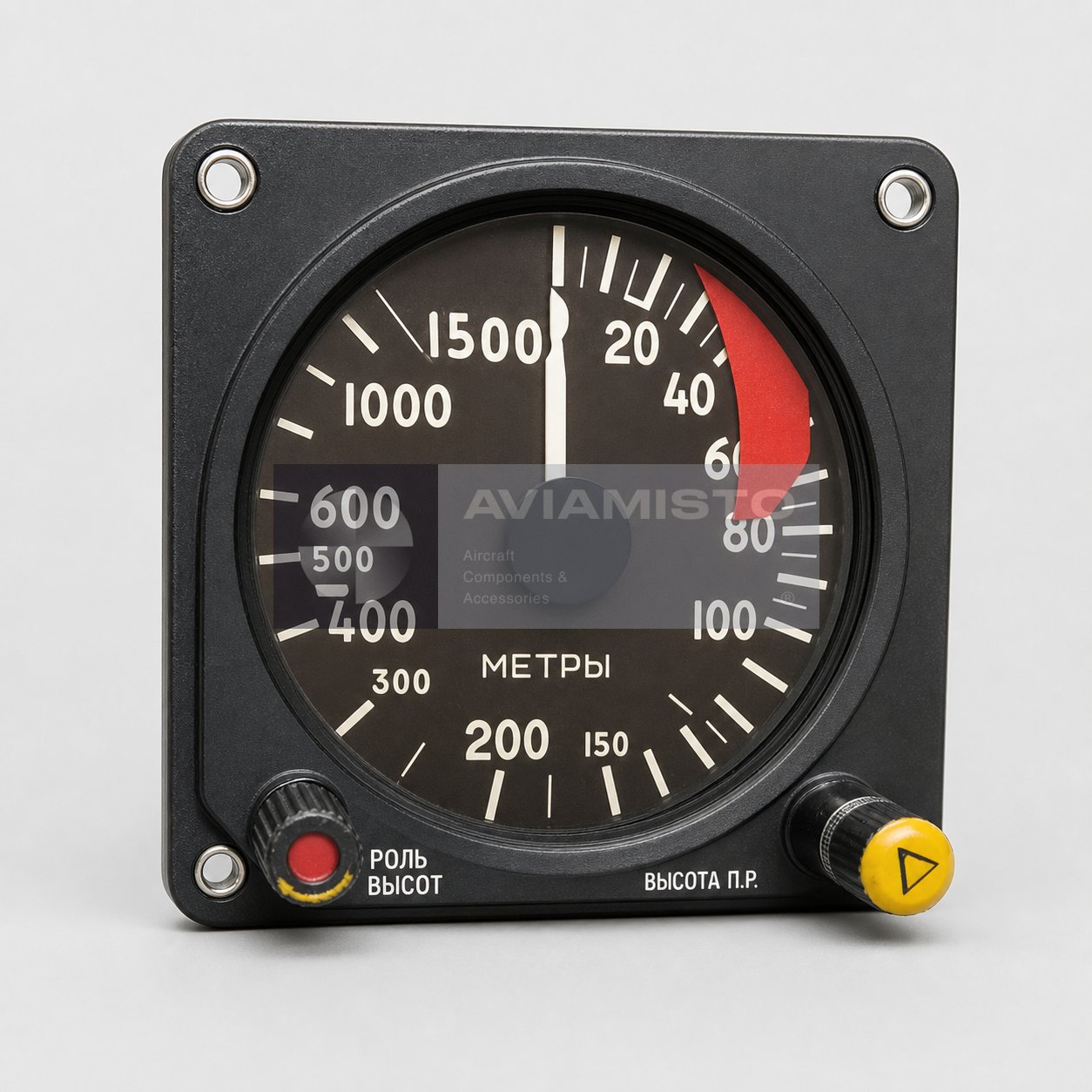
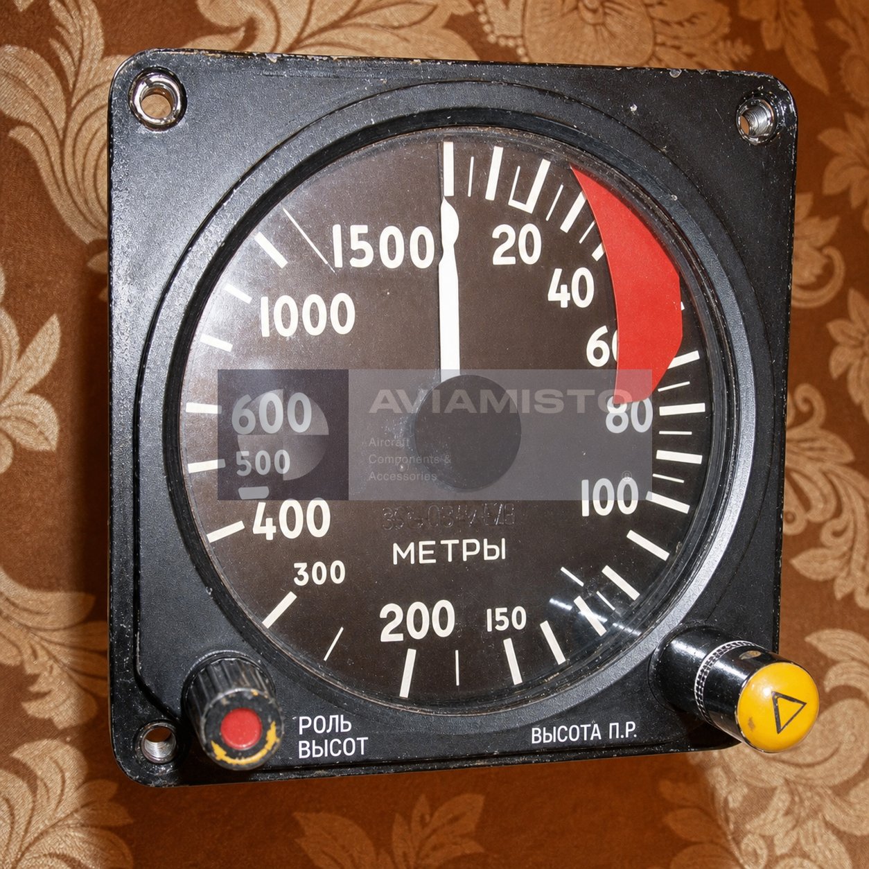
The supplied product photograph shows a non-linear metric scale extending from zero to 1500 metres. The lower range is expanded around the first tens and hundreds of metres, while the upper part of the scale is compressed. Visible reference values include 20, 40, 60, 80, 100, 150, 200, 300, 400, 500, 600, 1000 and 1500 m. This arrangement gives the pilot more visual resolution close to the ground without requiring a larger instrument face.
During operation, the main pointer follows the signal received from the radio-altimeter electronics. The reading represents clearance above the reflecting surface directly beneath the aircraft, not barometric altitude above sea level. Terrain relief, bank angle, antenna installation and the valid operating envelope of the associated system can influence when a reliable indication is available. The crew must therefore interpret the pointer together with the aircraft flight manual, warning indications and other flight instruments.
Danger-height setting and visual warning functions
A yellow rotary selector on the lower right of the face is used to set a danger-height reference. The selected threshold is represented on the scale by the associated index mechanism. When the aircraft descends through the preset radio height, the connected warning circuit can provide a visual or combined warning according to the installed radio-altimeter configuration. The lower-left red element forms part of the warning and control interface visible on this execution.
A red sector or flag on the scale is used as a reliability cue when the radio-altimeter signal cannot be used, the equipment is outside its valid range or a fault condition is detected. Exact behaviour depends on the complete system and must be checked in the relevant operating documentation. A serviceability check should include smooth pointer movement, correct operation of the height selector, flag response, illumination, connector condition and the system test mode. The scale and warning elements must remain clearly visible through the glass.
Interaction with A-037-family radio-altimeter equipment
The A-034-4 indicator family is associated with radio-altimeter installations such as the A-037 family and related low-altitude equipment. In a typical signal chain, antennas transmit and receive the radar signal, the transceiver processes the reflected signal and forms altitude information, and the cockpit indicator displays the result. The indicator also provides the crew interface for choosing a warning height and receiving fault or low-height cues.
Aviamisto catalogues related system equipment such as the A-037-1 transceiver and the A-037 Version 10 set. These links explain the general radio-altimeter architecture, but they do not establish automatic interchangeability with the -18 indicator. The exact transceiver, antenna set, cable and connector combination must be confirmed for the intended aircraft configuration.
Cockpit installation, applicability and ordering checks
The instrument is intended for recessed mounting in a pilot instrument panel. Its square front flange, four mounting points, circular scale and two lower controls remain accessible to the crew, while the cylindrical body and electrical connector are located behind the panel. Published supplier references associate A-034-4 indicators with several aircraft and helicopter installations. Mi-8-family helicopters and An-26 or An-72 aircraft are reported for related configurations, but exact applicability of A-034-4-18 should be treated as unconfirmed until it is matched to the aircraft component list.
Before ordering, compare the complete designation, 0–1500 m scale, dial language, illumination supply, connector, mounting depth and warning interface with the removed unit and aircraft documentation. The offered part should also be checked for passport, preservation record and test documentation when these are required. The product is listed in the Altimeters & Indicators category. Exact mass, overall dimensions, connector pinout, operating temperature and backlight supply for the -18 execution require confirmation from its own passport or technical conditions.
Technical details
- Product Type
- Pointer-type radio-altitude indicator
- Designation
- A-034-4-18
- Alternative Designations
- А-034-4-18; A034-4-18; A 034 4 18; А 034 4 18
- Function
- Cockpit indication of true height above terrain or water
- Measurement Role
- Display unit; altitude is measured and processed by the associated radio-altimeter equipment
All specificationsCollapse specifications
- System
- A-034-4 indicator family; A-037-family and compatible radio-altimeter installations
- Visible Indication Range
- 0–1500 m according to the supplied product photograph
- Scale Type
- Non-linear metric scale with expanded low-altitude section
- Visible Scale References
- 20; 40; 60; 80; 100; 150; 200; 300; 400; 500; 600; 1000; 1500 m
- Primary Indication
- Analog altitude pointer
- Danger-Height Control
- Manual rotary selector with scale index
- Warning / Reliability Indication
- Red warning element and red flag / sector depending on system state
- Operating Principle
- Electrical pointer indication from the processed radio-altimeter altitude signal
- Installation Area
- Pilot instrument panel
- Mounting
- Recessed panel installation with square front flange and four mounting points
- System-Level Signal Chain
- Antennas → radio-altimeter transceiver → A-034-4-18 cockpit indicator → visual / warning interface
- Related System Equipment
- A-037-1 transceiver; A-037 radio-altimeter set; exact compatibility requires documentation
- Reported / Unconfirmed Aircraft Applications
- Mi-8 family; An-26; An-72; confirm by aircraft equipment list
- Power and Backlight Supply
- Exact values for the A-034-4-18 execution require passport confirmation
- Accuracy
- Reliable execution-specific data were not found; do not apply 300 m version tolerances to this 1500 m scale
- Dimensions, Mass, Connector and Operating Temperature
- Reliable data for the exact A-034-4-18 execution were not found
- Technical Documentation
- Product passport, technical conditions, aircraft equipment list, wiring diagram and test records when available
Payment & delivery
Orders ship from our hub in Dubai. Partner stock is first transferred to Dubai, then shipped to you.
Dubai stock: 100% before dispatch. Partner stock (Remote stock) and Pre-order: 50% advance payment to start the order and 50% before shipment from Dubai to you.
Availability, lead time, delivery cost and payment terms are confirmed for your order before payment.
Payment & delivery terms