
V24-4301-100-7
Tail Support Shock Absorber

Description
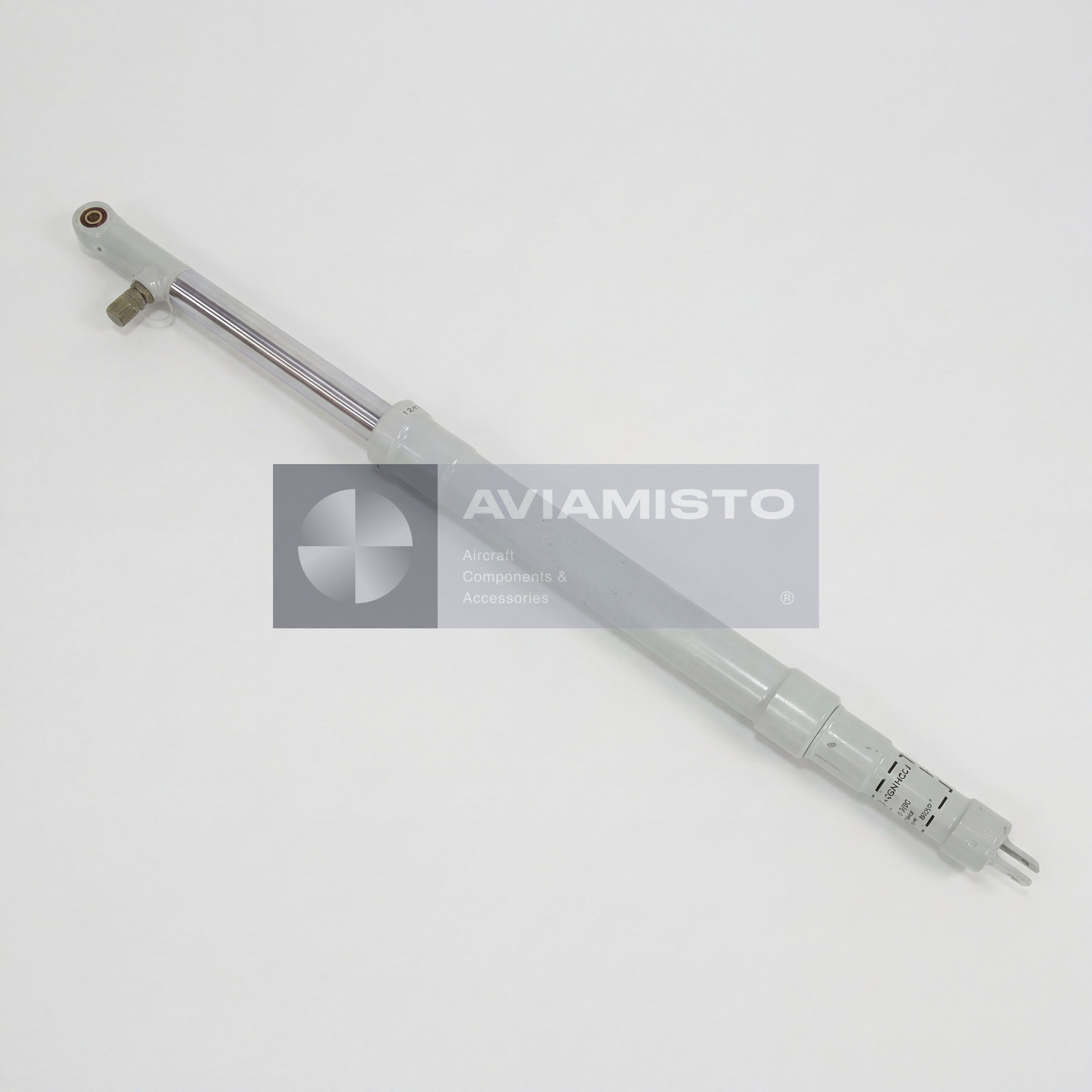
V24-4301-100-7 shock absorber in the tail support
The V24-4301-100-7 is a unified shock absorber used in the tail support assembly of Mi-8, Mi-17, Mi-171 and related helicopter modifications. This unit is installed in the rear lower part of the helicopter and protects the tail boom and tail rotor area from damage if the tail support touches the ground. Such contact may happen during landing with a high pitch angle, rough touchdown, ground maneuvering or excessive nose-up attitude. The shock absorber takes the impact through the tail support and reduces the load before it reaches the tail boom structure.
Full descriptionCollapse description
Tail boom protection with V24-4301-100-7
The tail support is not a normal landing gear leg used at every touchdown. It is a protective support that works when the rear part of the helicopter comes dangerously close to the ground. In that moment, the load path goes from the ground to the support pad, then into the shock absorber rod, through the cylinder and finally into the reinforced frame of the tail boom. The V24-4301-100-7 softens this load path. Without proper damping, the shock would be transmitted almost directly to the tail structure, braces and attachment points.
Installation position of the V24-4301-100-7 unit
The V24-4301-100-7 is mounted in the lower rear section of the fuselage, near the junction area of the tail boom and end boom, around reinforced frame No. 17. The unit is installed at an angle inside the tail support truss. The cylinder is attached through the upper eye to the reinforced tail boom fitting, while the rod is connected to the lower support structure and tail support pad assembly. This angled installation allows the shock absorber to compress when the tail support is loaded and then return to its extended position after the load is removed.
Oil and nitrogen operation of V24-4301-100-7
The V24-4301-100-7 is a liquid-gas, nitrogen-oil shock absorber. AMG-10 hydraulic oil works as the damping medium, while technical nitrogen creates the elastic force inside the cylinder. In normal parking condition, if the tail boom and support are not damaged, the rod should remain fully extended under internal nitrogen pressure. Compression takes place dynamically when the tail support contacts the ground. As the rod moves in, oil passes through internal restrictions and the nitrogen charge compresses. This absorbs energy and prevents a sharp rebound after impact.
Construction of the V24-4301-100-7 shock absorber
The unit consists of a steel cylinder, hollow rod, piston rings, upper and lower guide bushings, sealing cuffs and a charging valve located in the upper section. The internal oil volume is limited by the charging tube. These parts must hold pressure, guide the rod, keep the oil inside and allow controlled movement during impact. The condition of the rod surface, seals, bushings and charging valve is especially important. Oil traces on the rod, poor extension or loss of nitrogen pressure are signs that the unit needs attention before further aircraft operation.
Service checks for V24-4301-100-7
During scheduled maintenance, the V24-4301-100-7 is checked for nitrogen pressure, oil quantity, rod extension, leakage and general mechanical condition. Technicians inspect the rod for AMG-10 oil carry-over, check that the unit remains extended in parking condition and verify that the attachment points are secure. The sealing cuffs are also important, because leakage changes the damping behavior of the shock absorber. At repair facilities, specialized stands may be used to check operation, sealing quality and correct movement under load.
Mechanical links around V24-4301-100-7
The V24-4301-100-7 works together with the structural parts of the tail support. The upper cylinder eye is connected to the reinforced frame of the tail boom through a pin or bolt and transition bushing. The lower rod end connects with fork-type braces and the support pad assembly. These braces prevent side displacement and form a rigid support pyramid around the shock absorber. Bonding straps may also connect the tail support to the aircraft metal structure to discharge static electricity when the support contacts the ground.
Supply and documentation for V24-4301-100-7
For procurement, the full designation should be stated clearly: V24-4301-100-7, В24-4301-100-7 or B24-4301-100-7 depending on documentation style. The unit may be supplied as a standalone shock absorber with an individual passport or as part of an operational spare parts kit. For aircraft installation, condition matters: first category, storage item, repaired or overhauled unit should be confirmed before purchase. The passport should show identification, acceptance, storage or repair data, and any remaining service limits required for the helicopter maintenance records.
Confirmed installation context includes Mi-8 / Mi-17 family helicopters. Exact applicability of the individual execution must be checked against the illustrated parts catalogue and aircraft documentation.
Technical details
- Product Type
- Tail support shock absorber / tail landing gear shock absorber
- Designation
- V24-4301-100-7
- Alternative Designations
- В24-4301-100-7; B24-4301-100-7; V24-4301-100-7
- Base Model
- V24-4301-100, depending on documentation
- Function
- Absorption of impact energy when the tail support contacts the ground
All specificationsCollapse specifications
- Application / Where Used
- Helicopter tail support and landing gear protection systems
- System / Installation Area
- Tail support assembly, lower rear part of the tail boom
- Part of System / Included in Set
- Tail support / tail skid assembly
- Compatible Aircraft / Equipment
- Mi-8, Mi-8T, Mi-8MT, Mi-8MTV, Mi-8AMT / Mi-171, Mi-17 and related modifications
- Operating Principle
- Single-chamber liquid-gas shock absorber
- Working Fluid
- AMG-10 hydraulic oil, GOST 6794-74
- Oil Quantity
- 330 cm³ / 330 ±10 cm³ according to technical description
- Charging Gas
- Technical nitrogen, GOST 9293-74
- Nitrogen Charging Pressure
- 27 ±1 kgf/cm² with the rod fully extended
- Rod Position in Parking Condition
- Fully extended under nitrogen pressure
- Full Rod Stroke
- 360 mm according to the latest supplied technical description
- Installation Location
- Lower rear fuselage / tail boom area, around reinforced frame No. 17
- Mounting Position
- Inclined installation inside the tail support truss
- Upper Attachment
- Cylinder eye attached to reinforced frame No. 17 through pin / bolt and transition bushing
- Lower Attachment
- Rod connected with fork-type braces and support pad assembly
- Main Design Elements
- Steel cylinder, hollow rod, piston rings, upper and lower guide bushings, sealing cuffs, charging valve
- Bonding / Grounding
- Flexible bonding straps to the aircraft metal structure where installed
- Scope of Supply
- Shock absorber as a standalone unit or as part of operational spare parts kit 1E, depending on order
- Technical Documentation
- Individual product passport / manufacturer documentation
Payment & delivery
Orders ship from our hub in Dubai. Partner stock is first transferred to Dubai, then shipped to you.
Dubai stock: 100% before dispatch. Partner stock (Remote stock) and Pre-order: 50% advance payment to start the order and 50% before shipment from Dubai to you.
Availability, lead time, delivery cost and payment terms are confirmed for your order before payment.
Payment & delivery terms