
UP25/2
Reducing Valve
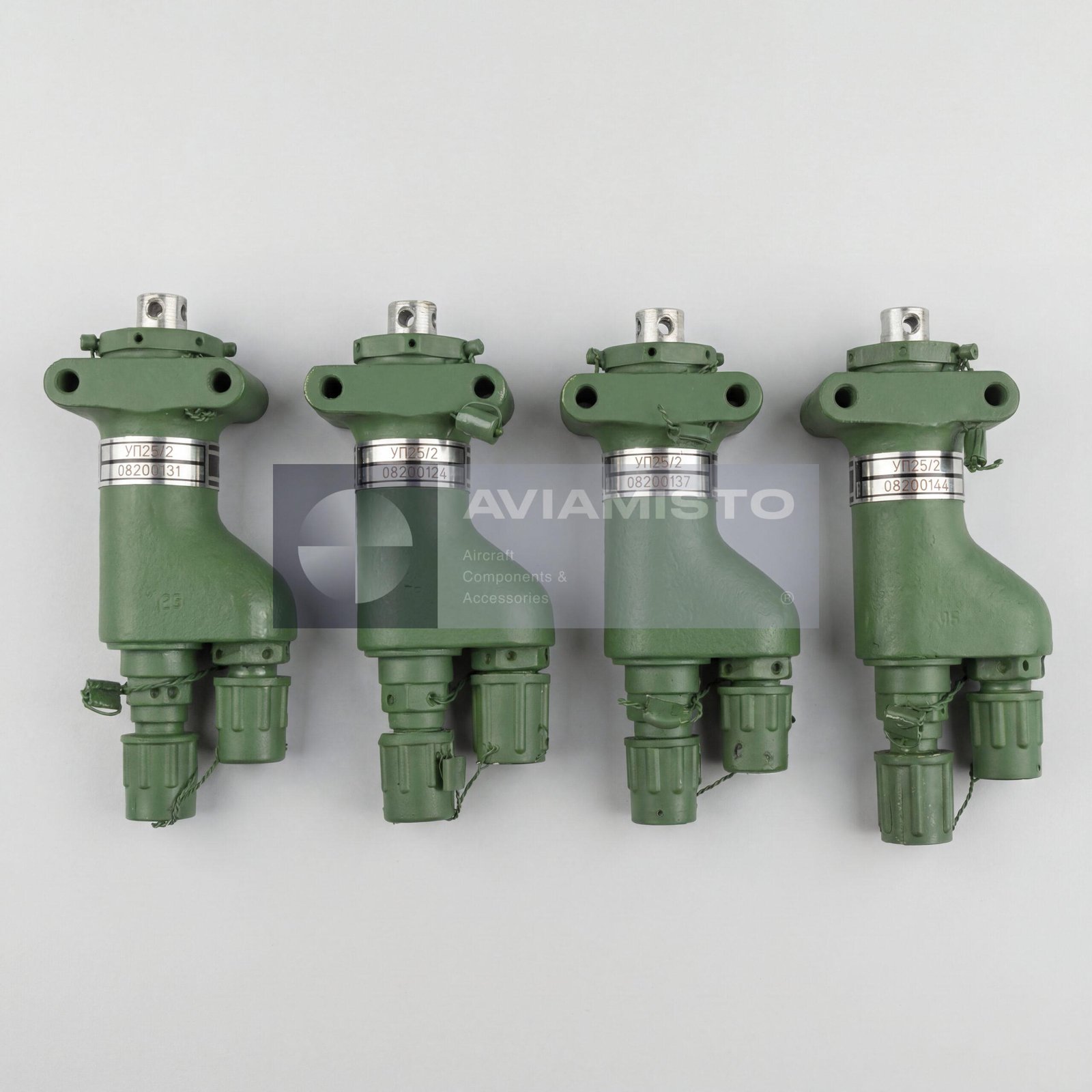
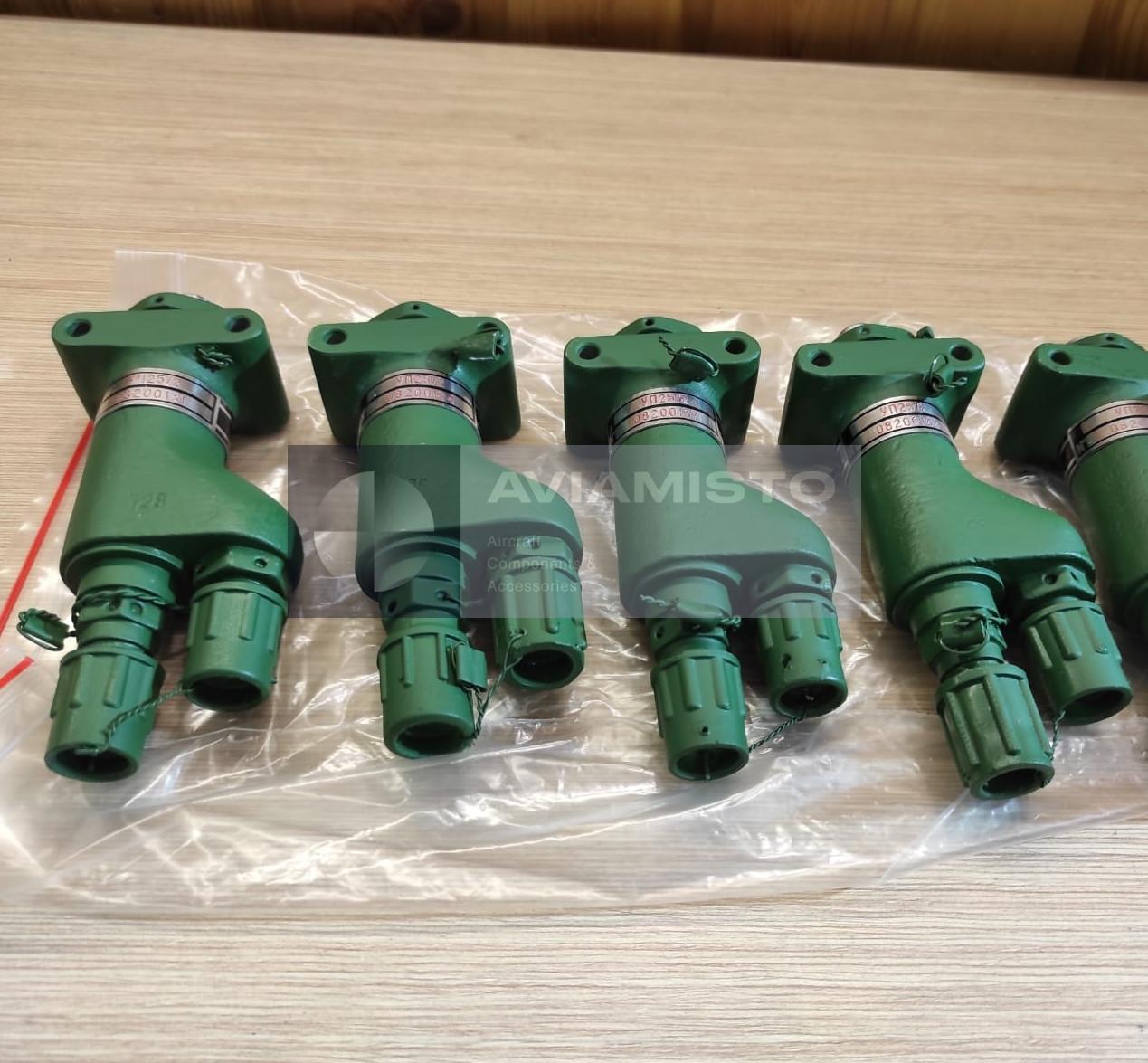
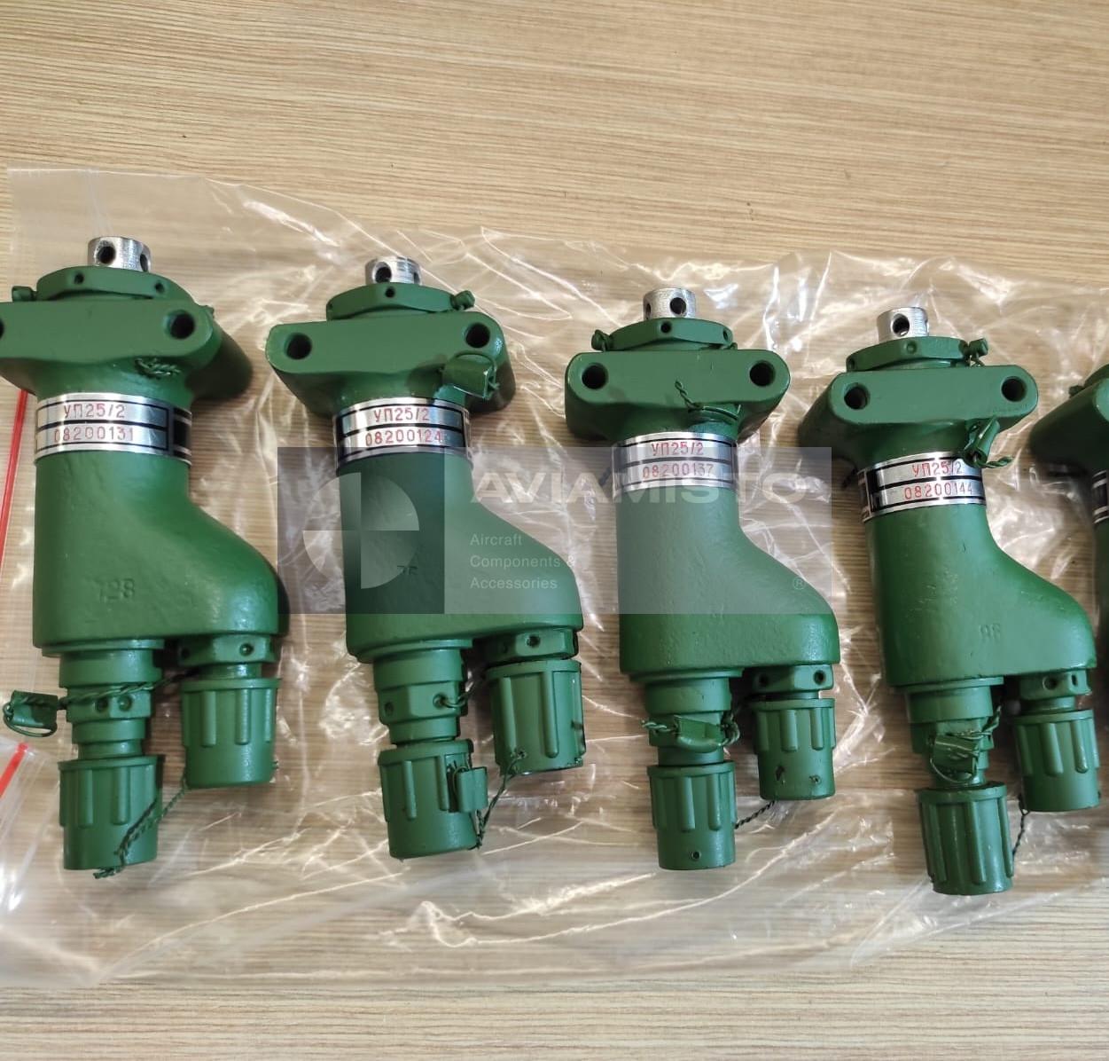
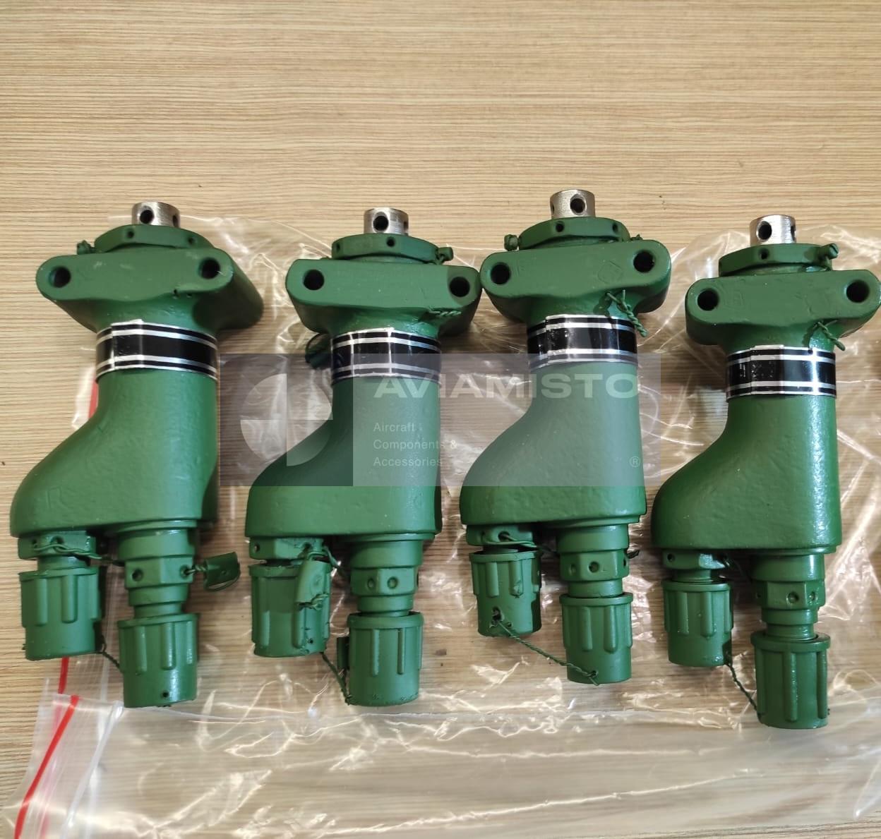


Description
UP25/2 reducing valve in the pneumatic brake system
The UP25/2 is an aircraft pneumatic reducing valve used in brake control systems of helicopters and aircraft. Its task is to reduce high-pressure air or nitrogen from the onboard pneumatic bottles and supply a lower, controlled pressure to the brake control circuit. The valve does not send full bottle pressure directly to the wheel brakes. Instead, it forms a regulated control pressure for downstream pneumatic brake units, which allows the braking process to be smoother, more proportional and safer for the landing gear system.
Full descriptionCollapse description
Pressure reduction function of the UP25/2
In aircraft pneumatic systems, the high-pressure line may operate at around 50 kgf/cm². This pressure must be reduced before it reaches brake control components. The UP25/2 lowers the incoming pressure and provides an adjustable outlet pressure within the required range. The output depends on the movement of the valve pusher, so the valve converts mechanical input from the control system into pneumatic control pressure. This is why the unit is important for accurate brake response during normal, emergency or auxiliary braking, depending on the aircraft configuration.
UP25/2 with brake accelerators and control units
In Mi-8 / Mi-17 type systems, the UP25/2 can work together with a reducing accelerator such as UPO-3/2 or UPO-3/2M. The UP25/2 supplies control pressure, while the accelerator handles the larger air flow sent to the brake actuating elements. In this layout, the UP25/2 is the command and pressure-reducing unit, not the final high-flow power valve. Depending on the aircraft type, it may also interact with differential braking components, front landing gear brake units or other pneumatic control devices.
Mechanical control of the UP25/2 valve
The UP25/2 is mechanically actuated. Control may come from the brake lever on the pilot’s control handle or from an automatic braking cylinder, depending on the aircraft system. When the pusher moves, the internal valve mechanism changes the balance between the high-pressure, low-pressure and control cavities. As a result, the valve changes the reduced outlet pressure. Correct linkage adjustment, smooth travel and absence of sticking are important. If the mechanical input is worn or incorrectly set, the brake system may respond too sharply, too weakly or with delay.
Internal layout of the UP25/2 reducing valve
The UP25/2 has a compact metal body with internal pneumatic cavities and sealing elements. The main internal zones are the high-pressure cavity, low-pressure cavity and control cavity. A diaphragm and valve elements separate these cavities and maintain the required pressure relationship. Tightness between internal sections is critical. Leakage or contamination may lead to unstable pressure reduction, slow response or incorrect brake control. During inspection, attention is usually paid to diaphragm condition, valve movement, pusher travel, sealing and cleanliness of pneumatic passages.
Aircraft application of UP25/2
The UP25/2 is used in pneumatic brake systems of various Soviet and Russian aircraft and helicopters, including Mi-8, Mi-17, Mi-171, An-2 and Il-62 applications depending on the system layout. On Mi-8 family helicopters, the valve is commonly associated with the emergency braking circuit of the main landing gear wheels and is installed under the cockpit floor area. On fixed-wing aircraft, it may be used in normal, backup or emergency pneumatic control circuits. Exact applicability should always be confirmed by the aircraft parts catalog and maintenance documentation.
Supply and identification of UP25/2
For procurement, the primary designation should be written as UP25/2, with UP-25/2 and Cyrillic variants listed as alternative designations. The aircraft type, brake system application, required condition and documentation should be stated in the request. The valve may be supplied as new, from storage, repaired or checked, depending on availability. For installation, the product passport or manufacturer documentation should confirm designation, acceptance status, storage or repair condition, and suitability for the required brake system configuration.
Related system equipment: UP03/2M, AK-50T1 Series 3, 723900-6AT. These items are grouped by system function and installation context, not as interchangeable replacements.
Confirmed installation context includes Mi-8 / Mi-17 family helicopters. Exact applicability of the individual execution must be checked against the illustrated parts catalogue and aircraft documentation.
Technical details
- Product Type
- Aircraft pneumatic reducing valve
- Designation
- UP25/2
- Alternative Designations
- UP-25/2; УП25/2; УП-25/2
- Function
- Reduction of high-pressure air or nitrogen and supply of controlled brake pressure
- Application / Where Used
- Aircraft and helicopter pneumatic brake systems
All specificationsCollapse specifications
- System / Installation Area
- Brake control system, normal or emergency braking circuit depending on aircraft configuration
- Compatible Aircraft / Equipment
- Mi-8, Mi-17, Mi-171, An-2, Il-62 and other aircraft depending on pneumatic system layout
- Working Medium
- Compressed air or technical nitrogen
- Inlet Pressure
- Nominal 50 kgf/cm² / 5 MPa
- Permissible Inlet Pressure Range
- Approximately 45–60 kgf/cm², according to supplied technical description
- Outlet / Reduced Pressure Range
- 0–11.5 kgf/cm² / 0–1.15 MPa
- Control Principle
- Mechanical actuation through brake lever or automatic braking cylinder depending on system configuration
- Internal Cavities
- High-pressure cavity, low-pressure cavity and control cavity
- Main Sealing Element
- Internal diaphragm / membrane
- Associated Components
- UPO-3/2, UPO-3/2M, UP-24/2, UP-45/1 differential unit, UG-108/1 depending on aircraft configuration
- Typical Mi-8 Installation Area
- Under cockpit floor, around frames No. 3N–4N according to supplied technical description
- Dimensions
- 120 × 55 × 35 mm
- Weight
- Approximately 0.3 kg
- Operating Temperature Range
- −55 to +55 °C
- Technical Documentation
- Product passport / manufacturer documentation
Payment & delivery
Orders ship from our hub in Dubai. Partner stock is first transferred to Dubai, then shipped to you.
Dubai stock: 100% before dispatch. Partner stock (Remote stock) and Pre-order: 50% advance payment to start the order and 50% before shipment from Dubai to you.
Availability, lead time, delivery cost and payment terms are confirmed for your order before payment.
In-person viewing of parts held in stock at our Dubai warehouse can be arranged on request.
Payment & delivery terms