
SSP-FK-BI Series 2
Block
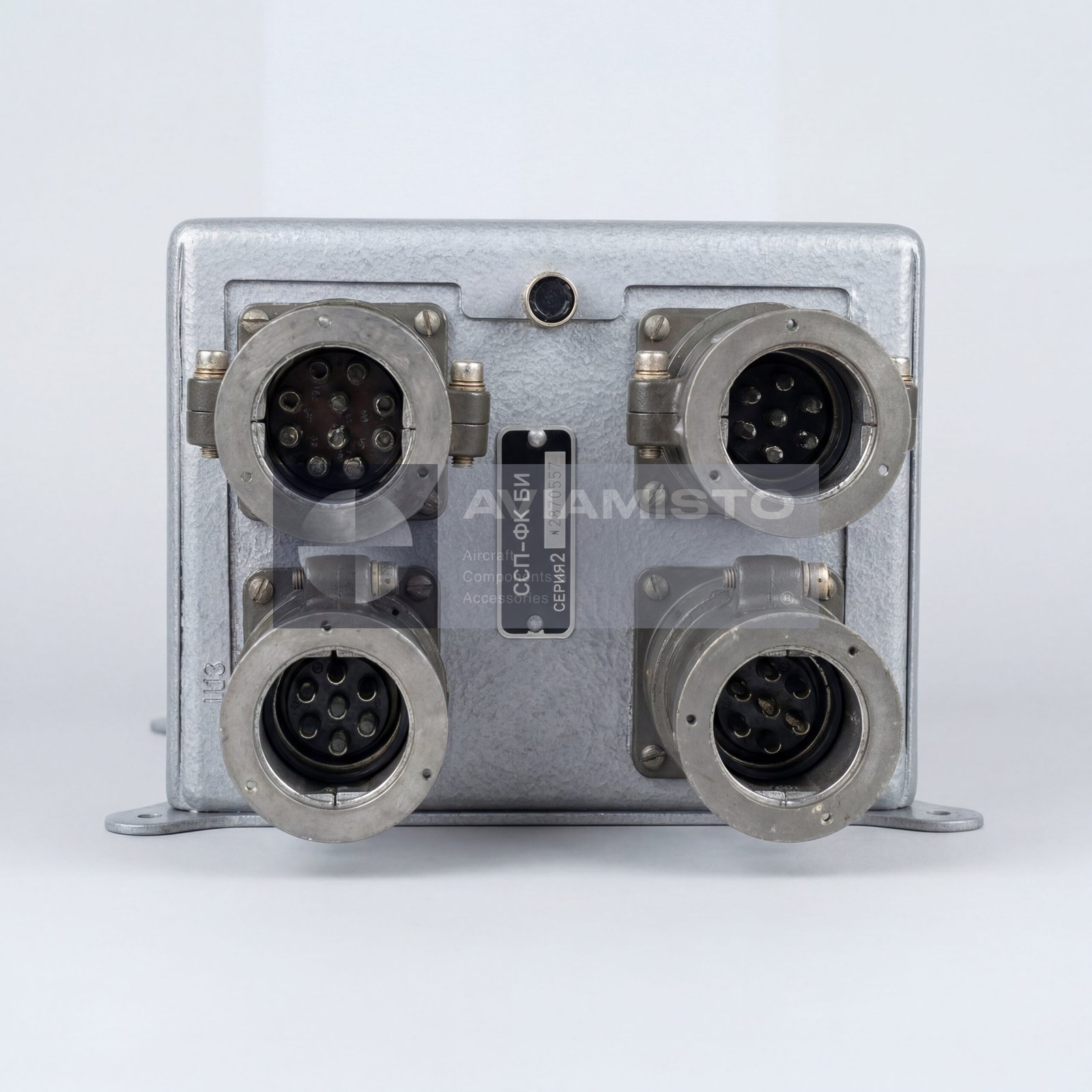


Description
SSP-FK-BI Series 2 block in the SSP-FK system
The SSP-FK-BI Series 2 is the executive block of the SSP-FK aircraft fire warning system. It receives signals from thermal fire sensors installed in protected aircraft compartments and forms the output commands for cockpit warning and fire-protection circuits. In practical terms, this block is the central switching and processing unit of the system. It connects sensor loops from engine bays, gearbox compartments or other fire-risk zones with warning lamps, sound indication, system test circuits and, depending on aircraft configuration, fire-extinguisher release circuits.
Full descriptionCollapse description
Fire signal processing by the SSP-FK-BI Series 2
The SSP-FK-BI Series 2 continuously monitors signals from connected fire sensors, typically DTBG or DPS type sensors according to the aircraft documentation. The system reacts to fire conditions by evaluating the signal produced by sensor groups installed in the protected zones. When the required threshold is reached, the block switches the corresponding output circuits and sends a fire signal to the cockpit indication system. The block itself does not detect flame visually and does not store extinguishing agent. It processes electrical sensor signals and activates the required aircraft circuits.
SSP-FK-BI Series 2 and fire-extinguishing control
Besides warning the crew, the SSP-FK-BI Series 2 may take part in the control chain for fire-extinguishing bottle actuation. In aircraft systems, this can include electrical circuits leading to pyrotechnic cartridges on fire-extinguisher bottle valve heads. Depending on the aircraft logic, the release may be automatic or commanded manually from the pilot’s fire-protection panel. This means the block should always be checked as part of the complete fire-protection system: sensors, wiring, cockpit controls, warning lamps, circuit breakers, pyrotechnic release circuits and extinguisher bottles all matter.
Installation of the SSP-FK-BI Series 2 block
The SSP-FK-BI Series 2 is usually installed in a technical or radio compartment, away from the protected hot zones. On Mi-8 / Mi-17 family helicopters, blocks of this type may be installed in the radio compartment or another dedicated equipment area depending on the modification. The location protects the block from direct heat exposure while keeping it connected to the sensor harnesses and aircraft control circuits. Before replacement, the installer should check the mounting position, connector type, wiring diagram, controlled zones and aircraft modification.
Channels and sensor groups of SSP-FK-BI Series 2
One SSP-FK-BI Series 2 block can serve several independent fire-warning channels. The actual number of zones and connected sensors depends on the aircraft installation. In a typical system, sensors are connected in groups and routed to individual channels so that the aircraft can identify the protected area where the fire signal appeared. Some configurations use multiple SSP-FK-BI blocks on one aircraft, especially where several protected compartments are covered. For supply and repair, the channel count and sensor grouping should be checked against the aircraft wiring scheme.
Built-in test and cockpit interaction
The SSP-FK-BI Series 2 supports operational system checks from the cockpit without releasing the extinguishing agent. This is important during pre-flight and maintenance procedures, because the crew or technician must verify the warning circuits before operation. The block interacts with fire-protection switches, test selectors, warning lamps, circuit protection devices and other aircraft systems. In some aircraft, the fire warning signal may also be connected with voice warning equipment or flight data recording systems. These connections depend on the specific aircraft electrical scheme.
Supply and identification of SSP-FK-BI Series 2
When ordering the block, the full designation SSP-FK-BI Series 2 should be stated together with the decimal drawing number DM4.568.019-01 if required. It is also useful to specify whether the request is for one executive block, a complete SSP-FK system set, sensors, sockets, connectors or wiring accessories. Before installation, the block should be checked by passport, storage condition, connector integrity, category, serviceability, compatibility with DTBG / DPS sensors and compliance with the fire-warning system documentation of the aircraft.
Related system equipment: SSP-FK Series 2, DPS, SSP-2I-RM. These positions are grouped by system function and installation context, not as interchangeable replacements.
Technical details
- Product Type
- Aircraft fire warning system executive block
- Designation
- SSP-FK-BI Series 2 / ССП-ФК-БИ серия 2
- Decimal Drawing Number
- DM4.568.019-01 / ДМ4.568.019-01
- Function
- Processing of fire sensor signals and output of warning / fire-protection commands
- Application / Where Used
- Aircraft and helicopter fire warning and fire-protection systems
All specificationsCollapse specifications
- Parent System
- SSP-FK / SSP-FK Series 2 fire warning system
- System / Installation Area
- Technical compartment, radio compartment or dedicated avionics/equipment area depending on aircraft type
- Typical Aircraft Application
- Mi-8 / Mi-17 family helicopters and other Soviet / Russian aircraft depending on configuration
- Input Sensors
- DTBG / DPS thermal fire sensors, depending on aircraft documentation
- Power Supply
- 27 V DC
- Permitted Voltage Range
- 18–30 V DC
- Current Consumption in Standby Mode
- Not more than 0.25 A, excluding actuation currents of release circuits
- Number of Controlled Channels
- Up to 6 independent zones / directions, depending on configuration
- Maximum Number of Connected Sensors
- Up to 36 DTBG or DPS sensors
- Typical Sensor Grouping
- Up to 6 sensors connected in series per channel, depending on aircraft wiring scheme
- Fire Detection Criteria
- Temperature above +150 °C or temperature rise rate above approximately 2–3 °C/s, determined by sensor characteristics
- Response Time / Inertia
- Not more than 10–15 s after reaching critical temperature conditions
- Operating Temperature Range
- −60 to +70 °C
- Relative Humidity
- Up to 98% at +35 °C
- Vibration Resistance
- 20–80 Hz with acceleration up to 2.3 g
- Approximate Weight
- 3.2–3.5 kg depending on housing modification
- System Kit Elements
- SSP-FK-BI executive block, DTBG / DPS sensors, SSP-2I-RM sensor sockets, connectors and related installation parts depending on aircraft set
- Associated Cockpit Controls
- Fire-protection switch, test selector, extinguisher actuation buttons depending on aircraft configuration
- Associated Indication
- Fire warning lamps / “FIRE” annunciators and sound warning circuits
- Associated Protection Devices
- AZSGK-Sh type circuit breakers, depending on aircraft scheme
- Associated Release Elements
- Pyrotechnic cartridges on fire-extinguisher bottle heads for first and second discharge stages, depending on aircraft configuration
- Related Aircraft Systems
- Voice warning equipment and flight recorder interfaces may be connected depending on aircraft wiring
- Typical Supply Category
- New / first set or category 1 from storage, subject to availability and documentation
- Technical Documentation
- Product passport, fire warning system documentation and aircraft maintenance documentation as applicable
Payment & delivery
Orders ship from our hub in Dubai. Partner stock is first transferred to Dubai, then shipped to you.
Dubai stock: 100% before dispatch. Partner stock (Remote stock) and Pre-order: 50% advance payment to start the order and 50% before shipment from Dubai to you.
Availability, lead time, delivery cost and payment terms are confirmed for your order before payment.
In-person viewing of parts held in stock at our Dubai warehouse can be arranged on request.
Payment & delivery terms