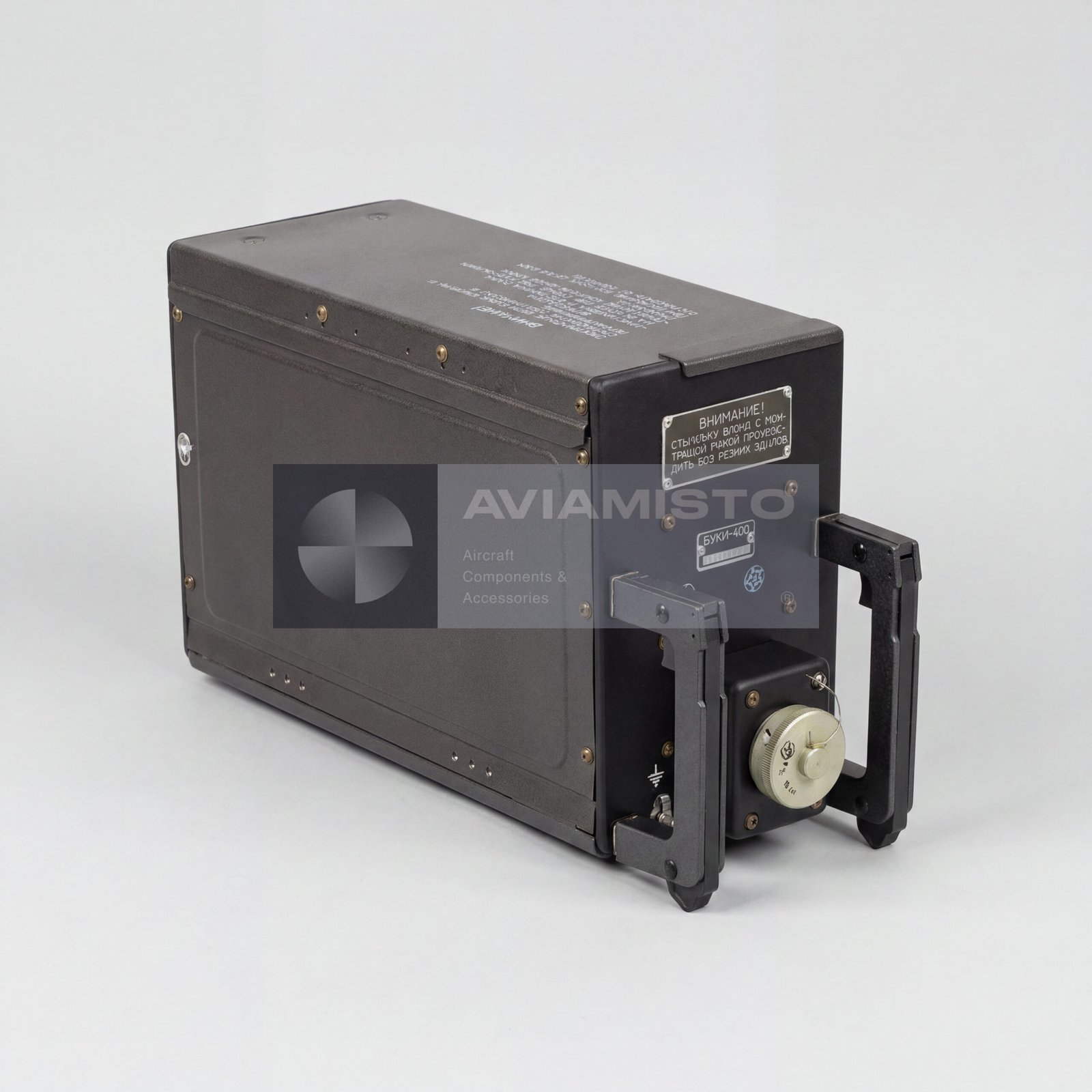
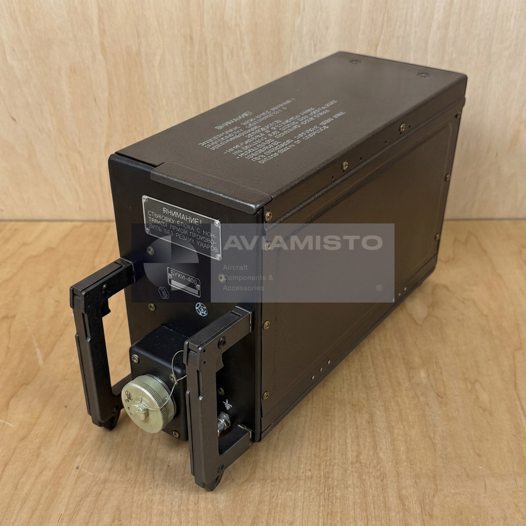
BUKI-400 Spoiler Control Unit for An-74
×

Login by Email

Custom order 0
Back to catalog
PARTNER STOCK
PARTNER STOCK

Control Unit

BUKI-400

Condition:New
Warranty:6 Months
Price on request
Price on request

Description

BUKI-400 in the aircraft spoiler control system

The BUKI-400 is an aircraft spoiler control and monitoring unit used in the onboard control system of wing spoiler panels. It belongs to aircraft avionics and electrical control equipment and is associated with the wing high-lift and flight-control systems of An-72 and An-74 aircraft, including An-74 modifications such as An-74TK-100. The unit receives control and feedback signals, processes them and generates electrical commands for the spoiler control system. In operation, BUKI-400 helps coordinate spoiler actuation, system monitoring and failure indication for the flight crew.

Control functions of the BUKI-400 unit

The BUKI-400 forms and distributes control signals for spoiler actuation. These signals are used by electrohydraulic valves, actuators or steering units that control the movement of spoiler panels. Depending on aircraft configuration and operating mode, the unit may support separate or synchronized control of left and right spoiler groups, including brake spoilers and aileron-spoilers. This makes the unit part of the logic chain between cockpit commands, aircraft sensors, hydraulic actuators and actual spoiler panel movement.

BUKI-400 operating modes

The spoiler system may work in manual and automatic modes, depending on aircraft logic. In manual mode, spoiler deployment is commanded from the cockpit control handle or lever on the pilots’ central panel. In automatic mode, spoiler deployment may be linked to landing conditions, including signals from landing gear shock strut compression switches after touchdown. The BUKI-400 processes these inputs and supports the required control response. This is especially important during landing rollout, when spoiler deployment helps reduce lift and improve braking effectiveness.

Monitoring and failure control by BUKI-400

Besides command formation, the BUKI-400 performs monitoring functions. It checks the condition of control channels and participates in failure indication to the crew. The unit receives signals from position sensors and control circuits, compares input values and monitors the operation of connected channels. If the system detects abnormal behavior, loss of signal or channel mismatch, warning information may be sent to cockpit indicators or central annunciation panels. This monitoring role is important because spoilers affect aircraft controllability and landing performance.

BUKI-400 interaction with aircraft systems

The BUKI-400 is integrated with several aircraft systems. It receives commands from spoiler controls in the cockpit, interacts with roll-control channels or related control-wheel position sensors where applicable, receives landing gear compression signals, and sends commands to hydraulic control elements. It is powered from the aircraft 27 V DC network. In typical system architecture, the unit may also work together with other wing mechanization control units, including the BUKZ-400 flap control and monitoring unit, depending on aircraft configuration.

Electrical signals and sensor interfaces of BUKI-400

The BUKI-400 works with the aircraft DC power network and with potentiometric sensor circuits. It supplies reference voltage to potentiometric sensors and receives variable input signals from them. These values are used for control logic and position monitoring. Correct operation depends on stable supply voltage, clean connector contacts, proper sensor adjustment and correct wiring in the aircraft harness. During troubleshooting, technicians usually check supply voltage, sensor voltage ranges, channel balance, output signals and actuation thresholds.

Installation and maintenance of BUKI-400

The BUKI-400 is built as a removable aircraft block for installation in onboard equipment racks, radio compartments or dedicated mounting frames, depending on the aircraft layout. The unit has a rear connector and is normally checked using specialized ground test equipment. Maintenance and repair are performed on test benches with DC power distribution and measuring instruments such as voltmeters and signal simulators. For aircraft installation, visual inspection alone is not enough; the unit must be checked by control signals, output response, monitoring channels and documentation.

Supply and documentation for BUKI-400

For supply, the unit should be requested by its full designation: BUKI-400 spoiler control and monitoring unit. The aircraft type, required condition, documentation and modification status should be confirmed before shipment. Since this is a control and monitoring unit for aircraft wing systems, interchangeability and serviceability must be verified through aircraft maintenance documentation, wiring diagrams and bench-test records. When supplied from storage or after repair, the passport, acceptance records and test results are important for confirming suitability for installation.

Details

Product Type: Spoiler control and monitoring unit
Designation: BUKI-400
Alternative Designations: БУКИ-400; BUKI-400
Function: Formation, distribution and monitoring of spoiler control signals
Application / Where Used: Aircraft spoiler and wing mechanization control systems
System / Installation Area: Wing spoiler control system; onboard avionics / equipment rack area
Part of System / Included in Set: Spoiler control and monitoring system
Compatible Aircraft / Equipment: An-72, An-74 and An-74 modifications, including An-74TK-100 depending on aircraft configuration
Related Unit: BUKZ-400 flap control and monitoring unit, depending on system configuration
Controlled Equipment: Electrohydraulic valves, spoiler actuators / steering units, spoiler panel control circuits depending on aircraft configuration
Operating Modes: Manual and automatic control modes
Control Channels: Separate or synchronized control of left and right spoiler groups depending on system configuration
Supply Voltage: 27 V DC
Supply Voltage Range: 24–29.4 V DC
Consumption Current: Not more than 10 A
Output Voltage for Potentiometric Sensor Supply: 9.4–10.3 V
Input Voltage from Potentiometric Sensors: 0.5–9.5 V
Power Consumption per Typical Channel: Not more than 100 W
Unit Actuation Voltage at Signal Difference: +0.35 − (0.35 ±0.07) ±0.07 V, according to supplied data
Operating Mode: Continuous / long-term
Operating Temperature Range: −60 to +60 °C
Housing Type: Removable aircraft block for rack or compartment installation
Overall Dimensions: 380 × 131 × 196 mm
Weight: Not more than 7.3 kg
Testing / Maintenance: Ground test bench check with DC power supply and measuring equipment
Technical Documentation: Aircraft maintenance documentation, wiring diagrams, passport / test documentation as applicable

Payment & delivery

All shipments are carried out from our international warehouse in Dubai (UAE), as well as from our partners’ remote warehouses.

In Stock — items available in stock at the Dubai warehouse are dispatched within 5–10 business days after receiving 100% prepayment.

Remote Stock — items available at our partners’ remote warehouses are supplied within an average of 30–45 business days after receiving 100% prepayment.

Pre-Order — made-to-order products are manufactured and delivered within an average of 45–60 business days. Payment terms: 50% advance payment to start production, with the remaining 50% paid before dispatch from the Dubai warehouse after full readiness for shipment.

Returns & Changes (Restocking Fee)
For selected items, a RESTOCKING FEE of 10% may apply in case of return, order cancellation, or changes to the order specifications. This condition applies only to certain products and is confirmed at the order approval stage.

Warranty
All products are covered by a standard 6-month warranty.
Extended warranty is available upon request and is agreed individually; it may affect the final product price.

  • Description
  • Details
  • Payment & delivery

BUKI-400 in the aircraft spoiler control system

The BUKI-400 is an aircraft spoiler control and monitoring unit used in the onboard control system of wing spoiler panels. It belongs to aircraft avionics and electrical control equipment and is associated with the wing high-lift and flight-control systems of An-72 and An-74 aircraft, including An-74 modifications such as An-74TK-100. The unit receives control and feedback signals, processes them and generates electrical commands for the spoiler control system. In operation, BUKI-400 helps coordinate spoiler actuation, system monitoring and failure indication for the flight crew.

Control functions of the BUKI-400 unit

The BUKI-400 forms and distributes control signals for spoiler actuation. These signals are used by electrohydraulic valves, actuators or steering units that control the movement of spoiler panels. Depending on aircraft configuration and operating mode, the unit may support separate or synchronized control of left and right spoiler groups, including brake spoilers and aileron-spoilers. This makes the unit part of the logic chain between cockpit commands, aircraft sensors, hydraulic actuators and actual spoiler panel movement.

BUKI-400 operating modes

The spoiler system may work in manual and automatic modes, depending on aircraft logic. In manual mode, spoiler deployment is commanded from the cockpit control handle or lever on the pilots’ central panel. In automatic mode, spoiler deployment may be linked to landing conditions, including signals from landing gear shock strut compression switches after touchdown. The BUKI-400 processes these inputs and supports the required control response. This is especially important during landing rollout, when spoiler deployment helps reduce lift and improve braking effectiveness.

Monitoring and failure control by BUKI-400

Besides command formation, the BUKI-400 performs monitoring functions. It checks the condition of control channels and participates in failure indication to the crew. The unit receives signals from position sensors and control circuits, compares input values and monitors the operation of connected channels. If the system detects abnormal behavior, loss of signal or channel mismatch, warning information may be sent to cockpit indicators or central annunciation panels. This monitoring role is important because spoilers affect aircraft controllability and landing performance.

BUKI-400 interaction with aircraft systems

The BUKI-400 is integrated with several aircraft systems. It receives commands from spoiler controls in the cockpit, interacts with roll-control channels or related control-wheel position sensors where applicable, receives landing gear compression signals, and sends commands to hydraulic control elements. It is powered from the aircraft 27 V DC network. In typical system architecture, the unit may also work together with other wing mechanization control units, including the BUKZ-400 flap control and monitoring unit, depending on aircraft configuration.

Electrical signals and sensor interfaces of BUKI-400

The BUKI-400 works with the aircraft DC power network and with potentiometric sensor circuits. It supplies reference voltage to potentiometric sensors and receives variable input signals from them. These values are used for control logic and position monitoring. Correct operation depends on stable supply voltage, clean connector contacts, proper sensor adjustment and correct wiring in the aircraft harness. During troubleshooting, technicians usually check supply voltage, sensor voltage ranges, channel balance, output signals and actuation thresholds.

Installation and maintenance of BUKI-400

The BUKI-400 is built as a removable aircraft block for installation in onboard equipment racks, radio compartments or dedicated mounting frames, depending on the aircraft layout. The unit has a rear connector and is normally checked using specialized ground test equipment. Maintenance and repair are performed on test benches with DC power distribution and measuring instruments such as voltmeters and signal simulators. For aircraft installation, visual inspection alone is not enough; the unit must be checked by control signals, output response, monitoring channels and documentation.

Supply and documentation for BUKI-400

For supply, the unit should be requested by its full designation: BUKI-400 spoiler control and monitoring unit. The aircraft type, required condition, documentation and modification status should be confirmed before shipment. Since this is a control and monitoring unit for aircraft wing systems, interchangeability and serviceability must be verified through aircraft maintenance documentation, wiring diagrams and bench-test records. When supplied from storage or after repair, the passport, acceptance records and test results are important for confirming suitability for installation.

Product Type: Spoiler control and monitoring unit
Designation: BUKI-400
Alternative Designations: БУКИ-400; BUKI-400
Function: Formation, distribution and monitoring of spoiler control signals
Application / Where Used: Aircraft spoiler and wing mechanization control systems
System / Installation Area: Wing spoiler control system; onboard avionics / equipment rack area
Part of System / Included in Set: Spoiler control and monitoring system
Compatible Aircraft / Equipment: An-72, An-74 and An-74 modifications, including An-74TK-100 depending on aircraft configuration
Related Unit: BUKZ-400 flap control and monitoring unit, depending on system configuration
Controlled Equipment: Electrohydraulic valves, spoiler actuators / steering units, spoiler panel control circuits depending on aircraft configuration
Operating Modes: Manual and automatic control modes
Control Channels: Separate or synchronized control of left and right spoiler groups depending on system configuration
Supply Voltage: 27 V DC
Supply Voltage Range: 24–29.4 V DC
Consumption Current: Not more than 10 A
Output Voltage for Potentiometric Sensor Supply: 9.4–10.3 V
Input Voltage from Potentiometric Sensors: 0.5–9.5 V
Power Consumption per Typical Channel: Not more than 100 W
Unit Actuation Voltage at Signal Difference: +0.35 − (0.35 ±0.07) ±0.07 V, according to supplied data
Operating Mode: Continuous / long-term
Operating Temperature Range: −60 to +60 °C
Housing Type: Removable aircraft block for rack or compartment installation
Overall Dimensions: 380 × 131 × 196 mm
Weight: Not more than 7.3 kg
Testing / Maintenance: Ground test bench check with DC power supply and measuring equipment
Technical Documentation: Aircraft maintenance documentation, wiring diagrams, passport / test documentation as applicable

All shipments are carried out from our international warehouse in Dubai (UAE), as well as from our partners’ remote warehouses.

In Stock — items available in stock at the Dubai warehouse are dispatched within 5–10 business days after receiving 100% prepayment.

Remote Stock — items available at our partners’ remote warehouses are supplied within an average of 30–45 business days after receiving 100% prepayment.

Pre-Order — made-to-order products are manufactured and delivered within an average of 45–60 business days. Payment terms: 50% advance payment to start production, with the remaining 50% paid before dispatch from the Dubai warehouse after full readiness for shipment.

Returns & Changes (Restocking Fee)
For selected items, a RESTOCKING FEE of 10% may apply in case of return, order cancellation, or changes to the order specifications. This condition applies only to certain products and is confirmed at the order approval stage.

Warranty
All products are covered by a standard 6-month warranty.
Extended warranty is available upon request and is agreed individually; it may affect the final product price.

Didn’t find the parts you need? Contact us — we will assist in sourcing them.

Send your request — we will provide availability, lead time, pricing, and delivery details.
Share